Search by part number and manufacturer or description
 File Size : 279.43KB
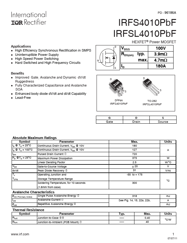
Applications l High Efficiency Synchronous Rectification in SMPS l Uninterruptible Power Supply l High Speed Power Switching l Hard Switched and High Frequency Circuits G Benefits l Improved Gate, Avalanche and Dynamic dV/dt Ruggedness l Fully Characterized Capacitance and Avalanche SOA l Enhanced.
mally limited) IAR EAR
dSingle Pulse Avalanche Energy cAvalanche Current fRepetitive Avalanche Energy
Thermal Resistance
Symbol RθJC RθJA
Parameter
jkJunction-to-Case iJunction-to-Ambient (PCB Mount)
www.irf.com
Max. 180 127 720 375 2.5 ± 20 31 -55 to + 175
300
318 See Fig. 14, 15, 22a, 22b,
Typ.
–
–
–
–
–
–
Max. 0.40 40
Units
A W W/°C V V/ns
°C
mJ A mJ
Units °C/W
1
07/07/11
IRFS/SL4010PbF
Static @ TJ = 25°C (unless otherwise specified)
Symbol
Parameter
Min.
V(BR)DSS ΔV(BR)DSS/ΔTJ RDS(on) VGS(th) IDSS
Drain-to-Source Breakdown Voltage Breakdown Voltage Temp. Coefficient Static Dra.


Similar Product
| No. | Part # | Manufacture | Description | Datasheet |
|---|---|---|---|---|
| 1 | IRFS4010 |

INCHANGE |
N-Channel MOSFET |

|
| 2 | IRFS4010-7PPbF |

International Rectifier |
Power MOSFET |
|
| 3 | IRFS4020PbF |
International Rectifier |
Digital Audio MOSFET |
|
| 4 | IRFS4020PBF |
INCHANGE |
N-Channel MOSFET |
|
| 5 | IRFS4115-7PPbF |
International Rectifier |
Power MOSFET |
|