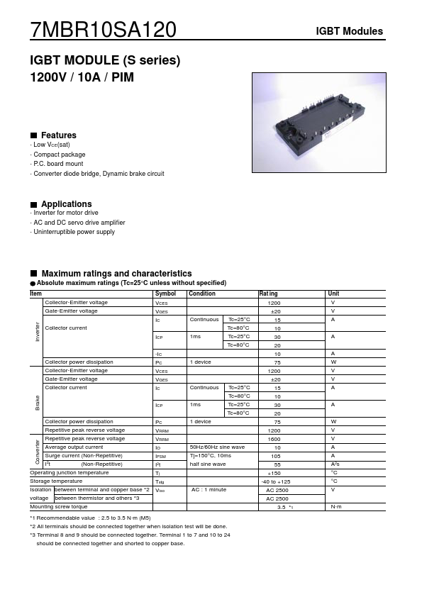
7MBR10SA120
IGBT MODULE (S series) 1200V / 10A / PIM
IGBT Modules
Features
· Low VCE(sat) · Compact package · P.C. boa...
7MBR10SA120
IGBT MODULE (S series) 1200V / 10A / PIM
IGBT Modules
Features
· Low VCE(sat) · Compact package · P.C. board mount · Converter diode bridge, Dynamic brake circuit
Applications
· Inverter for motor drive · AC and DC servo drive amplifier · Uninterruptible power supply
Maximum ratings and characteristics
Absolute maximum ratings (Tc=25°C unless without specified)
Item Collector-Emitter
voltage Gate-Emitter
voltage Inverter Collector current ICP -IC PC VCES VGES IC ICP Collector power dissipation Repetitive peak reverse
voltage Repetitive peak reverse
voltage Average output current Surge current (Non-Repetitive) I 2t (Non-Repetitive) PC VRRM VRRM IO IFSM I2 t Tj Tstg Viso 1ms Symbol VCES VGES IC Condition Rat ing 1200 ±20 15 10 30 20 10 75 1200 ±20 15 10 30 20 75 1200 1600 10 105 55 +150 -40 to +125 AC 2500 AC 2500 3.5 *1 Unit V V A A A W V V A A W V V A A A 2s °C °C V N·m
Continuous
Tc=25°C Tc=80°C Tc=25°C Tc=80°C
Collector power dissipation Collector-Emitter
voltage Gate-Emitter
voltage Collector current Brake
1 device
Continuous 1ms 1 device
Tc=25°C Tc=80°C Tc=25°C Tc=80°C
Converter
50Hz/60Hz sine wave Tj=150°C, 10ms half sine wave
Operating junction temperature Storage temperature Isolation between terminal and copper base *2
voltage between thermistor and others *3 Mounting screw torque
AC : 1 minute
*1 Recommendable value : 2.5 to 3.5 N·m (M5) *2 All terminals should be connected together when isolation test will be done. *3 Terminal 8 and 9 shou...