2918
OUT1A OUT2A E2 OUT2B LOAD SPLY SENSE 2
1 2 3 4 5 6 7 8 9
DUAL FULL-BRIDGE PWM MOTOR DRIVER
The A2918SWH and A2918S...
2918
OUT1A OUT2A E2 OUT2B LOAD SPLY SENSE 2
1 2 3 4 5 6 7 8 9
DUAL FULL-BRIDGE PWM MOTOR DRIVER
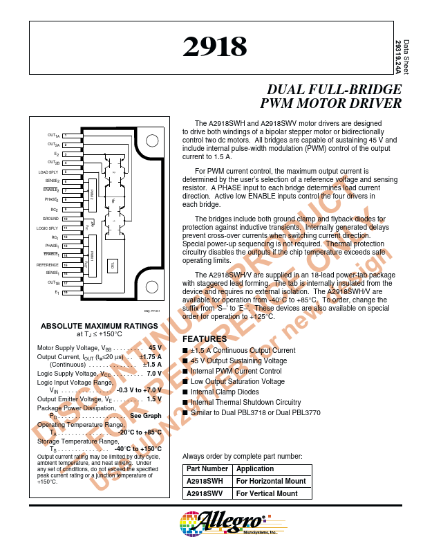
The A2918SWH and A2918SWV motor drivers are designed to drive both windings of a bipolar stepper motor or bidirectionally control two dc motors. All bridges are capable of sustaining 45 V and include internal pulse-width modulation (PWM) control of the output current to 1.5 A. For PWM current control, the maximum output current is determined by the user’s selection of a reference
voltage and sensing resistor. A PHASE input to each bridge determines load current direction. Active low ENABLE inputs control the four drivers in each bridge. The bridges include both ground clamp and flyback diodes for protection against inductive transients. Internally generated delays prevent cross-over currents when switching current direction. Special power-up sequencing is not required. Thermal protection circuitry disables the outputs if the chip temperature exceeds safe operating limits.
2
ENABLE2 PHASE2 RC2
GROUND LOGIC SPLY
REFERENCE
ABSOLUTE MAXIMUM RATINGS
at TJ ≤ +150°C
Motor Supply
Voltage, VBB . . . . . . . . . 45 V Output Current, IOUT (tw≤20 µs) . . ±1.75 A (Continuous) . . . . . . . . . . . . . . ±1.5 A Logic Supply
Voltage, VCC . . . . . . . . . 7.0 V Logic Input
Voltage Range, VIN . . . . . . . . . . . . . . . -0.3 V to +7.0 V Output Emitter
Voltage, VE . . . . . . . . . 1.5 V Package Power Dissipation, PD . . . . . . . . . . . . . . . . . . . . See Graph Operating Temperature Ra...