Data Sheet
12-Bit, 20 MSPS/40 MSPS/65 MSPS/80 MSPS, 1.8 V Analog-to-Digital Converter
AD9629
FEATURES
1.8 V analog sup...
Data Sheet
12-Bit, 20 MSPS/40 MSPS/65 MSPS/80 MSPS, 1.8 V Analog-to-Digital Converter
AD9629
FEATURES
1.8 V analog supply operation 1.8 V to 3.3 V output supply SNR
71.3 dBFS at 9.7 MHz input 69.0 dBFS at 200 MHz input SFDR 95 dBc at 9.7 MHz input 83 dBc at 200 MHz input Low power 45 mW at 20 MSPS 85 mW at 80 MSPS Differential input with 700 MHz bandwidth On-chip
voltage reference and sample-and-hold circuit 2 V p-p differential analog input DNL = ±0.16 LSB Serial port control options Offset binary, gray code, or twos complement data format Integer 1, 2, or 4 input clock divider Built-in selectable digital test pattern generation Energy-saving power-down modes Data clock out with programmable clock and data alignment
APPLICATIONS
Communications Diversity radio systems Multimode digital receivers
GSM, EDGE, W-CDMA, LTE, CDMA2000, WiMAX, TD-SCDMA Smart antenna systems Battery-powered instruments Hand held scope meters Portable medical imaging Ultrasound Radar/LIDAR PET/SPECT imaging
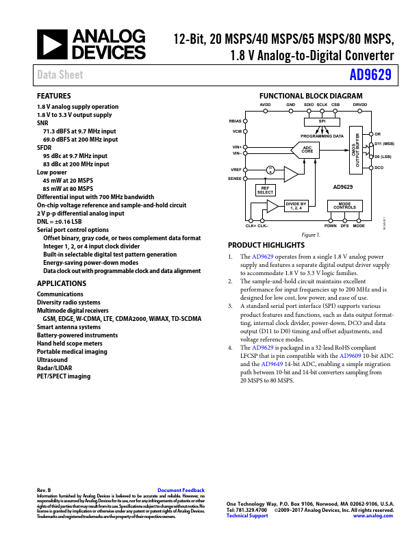
RBIAS VCM
VIN+ VIN–
VREF SENSE
FUNCTIONAL BLOCK DIAGRAM
AVDD
GND SDIO SCLK CSB
DRVDD
SPI PROGRAMMING DATA
ADC CORE
CMOS OUTPUT BUFFER
OR D11 (MSB) D0 (LSB) DCO
REF SELECT
DIVIDE BY 1, 2, 4
AD9629
MODE CONTROLS
08540-001
CLK+ CLK–
PDWN DFS MODE
Figure 1.
PRODUCT HIGHLIGHTS
1. The AD9629 operates from a single 1.8 V analog power supply and features a separate digital output driver supply to accommodate 1.8 V to 3.3 V logic families.
2. The sample-and-hold circuit maintains excellent...