Data Sheet
650 kHz /1.3 MHz Step-Up PWM DC-to-DC Switching Converters
ADP1612/ADP1613
FEATURES
Current limit 1.4 A for...
Data Sheet
650 kHz /1.3 MHz Step-Up PWM DC-to-DC Switching Converters
ADP1612/ADP1613
FEATURES
Current limit 1.4 A for the ADP1612 2.0 A for the ADP 1613
Minimum input
voltage 1.8 V for the ADP1612 2.5 V for the ADP1613
Pin-selectable 650 kHz or 1.3 MHz PWM frequency Adjustable output
voltage up to 20 V Adjustable soft start Under
voltage lockout Thermal shutdown 8-lead MSOP Supported by ADIsimPower™ design tool ADIsimPower downloadable design tools for boost, coupled-
SEPIC, and SEPIC Cuk configurations
APPLICATIONS
TFT LCD bias supplies
Portable applications
Industrial/instrumentation equipment
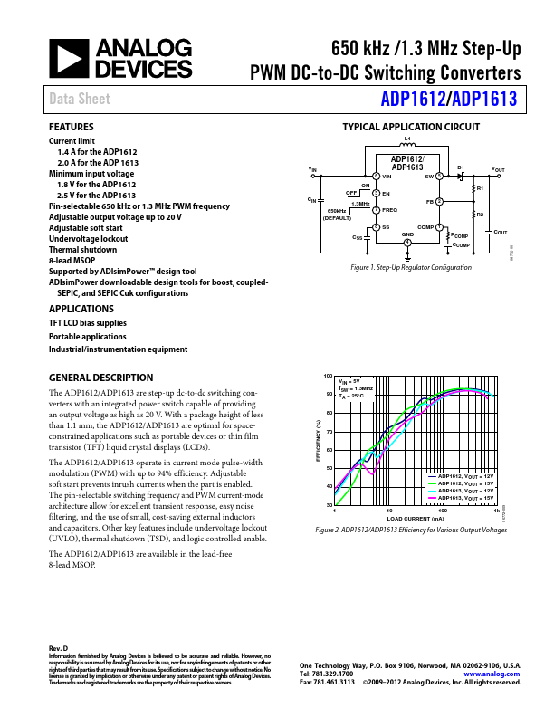
TYPICAL APPLICATION CIRCUIT
L1
ADP1612/
VIN ADP1613
6 VIN
SW 5
ON
OFF
3 EN
CIN 1.3MHz
650kHz
7 FREQ
(DEFAULT)
FB 2
8 SS
COMP 1
CSS
GND 4
D1 VOUT R1
R2
RCOMP CCOMP
COUT
Figure 1. Step-Up Regulator Configuration
06772-001
GENERAL DESCRIPTION
The ADP1612/ADP1613 are step-up dc-to-dc switching converters with an integrated power switch capable of providing an output
voltage as high as 20 V. With a package height of less than 1.1 mm, the ADP1612/ADP1613 are optimal for spaceconstrained applications such as portable devices or thin film transistor (TFT) liquid crystal displays (LCDs).
The ADP1612/ADP1613 operate in current mode pulse-width modulation (PWM) with up to 94% efficiency. Adjustable soft start prevents inrush currents when the part is enabled. The pin-selectable switching frequency and PWM current-mode architecture allow for excellent transient response,...