Analog Power
N-Channel 650-V (D-S) MOSFET
Key Features: • Low rDS(on) trench technology • Low thermal impedance • Fast s...
Analog Power
N-Channel 650-V (D-S)
MOSFET
Key Features: Low rDS(on) trench technology Low thermal impedance Fast switching speed
Typical Applications: Off-line Power Supplies Electronic Ballasts High Power LED Lighting
AM9N65P
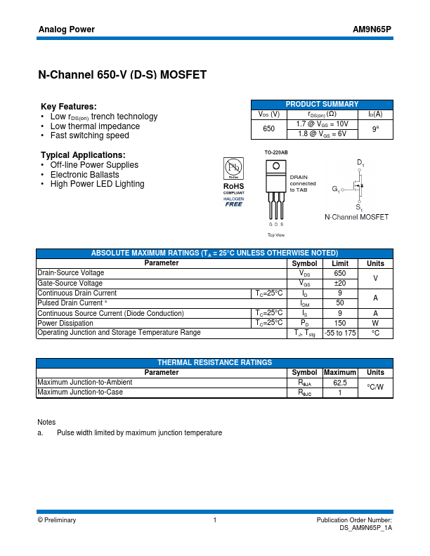
VDS (V) 650
PRODUCT SUMMARY rDS(on) (Ω)
1.7 @ VGS = 10V 1.8 @ VGS = 6V
ID(A) 9a
DRAIN connected to TAB
ABSOLUTE MAXIMUM RATINGS (TA = 25°C UNLESS OTHERWISE NOTED)
Parameter
Symbol Limit
Drain-Source
Voltage
VDS 650
Gate-Source
Voltage
VGS ±20
Continuous Drain Current Pulsed Drain Current a
TC=25°C
ID IDM
9 50
Continuous Source Current (Diode Conduction)
TC=25°C
IS
9
Power Dissipation
TC=25°C
PD
150
Operating Junction and Storage Temperature Range
TJ, Tstg -55 to 175
Units V
A A W °C
Maximum Junction-to-Ambient Maximum Junction-to-Case
THERMAL RESISTANCE RATINGS Parameter
Symbol RθJA RθJC
Maximum 62.5 1
Units °C/W
Notes a. Pulse width limited by maximum junction temperature
© Preliminary
1 Publication Order Number: DS_AM9N65P_1A
Analog Power
AM9N65P
Electrical Characteristics
Parameter
Symbol
Test Conditions
Min Typ Max Unit
Static
Gate-Source Threshold
Voltage Gate-Body Leakage
Zero Gate
Voltage Drain Current
On-State Drain Current a Drain-Source On-Resistance a
Forward Transconductance a Diode Forward
Voltage a
VGS(th) IGSS
IDSS
ID(on)
rDS(on)
gfs VSD
VDS = VGS, ID = 250 uA VDS = 0 V, VGS = ±20 V VDS = 520 V, VGS = 0 V VDS = 520 V, VGS = 0 V, TJ = 55°C VDS = 5 V, VGS = 10 V
VGS = 10 V, ID = 3 A ...