www.DataSheet4U.com
www.fairchildsemi.com
AN-6003
“Shoot-through” in Synchronous Buck Converters
Jon Klein Power Manag...
www.DataSheet4U.com
www.fairchildsemi.com
AN-6003
“Shoot-through” in Synchronous Buck Converters
Jon Klein Power Management Applications
Abstract
The synchronous buck circuit is in widespread use to provide “point of use” high current, low
voltage power for CPU’s, chipsets, peripherals etc. In the synchronous buck converter, the power stage has a “high-side” (Q1 below)
MOSFET to charge the inductor, and a “Low-side”
MOSFET which replaces a conventional buck regulator’s “catch diode” to provide a low-loss recirculation path for the inductor current.
V IN
PWM CONTROLLER
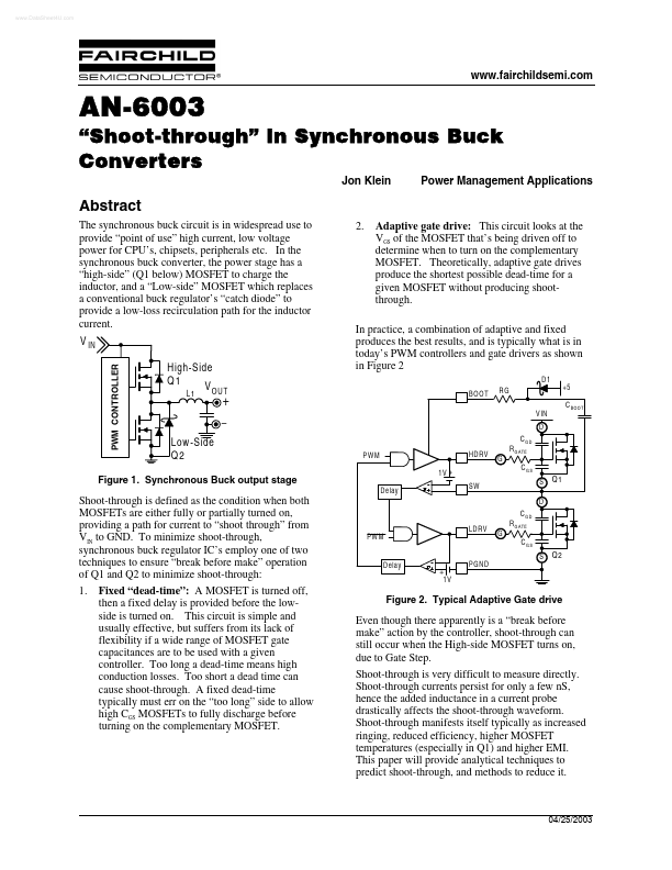
2.
Adaptive gate drive: This circuit looks at the VGS of the
MOSFET that’s being driven off to determine when to turn on the complementary
MOSFET. Theoretically, adaptive gate drives produce the shortest possible dead-time for a given
MOSFET without producing shootthrough.
H igh-S ide Q1 VO U T
L1
In practice, a combination of adaptive and fixed produces the best results, and is typically what is in today’s PWM controllers and gate drivers as shown in Figure 2
D1 BOOT RG V IN +5 C BO O T
+
–
D C GD PW M 1V + D elay SW H D RV R G A TE G C GS S D C GD LDR V PW M R G A TE G C GS S D elay + 1V PG ND
Low -S ide Q2
Figure 1. Synchronous Buck output stage
Q1
Shoot-through is defined as the condition when both
MOSFETs are either fully or partially turned on, providing a path for current to “shoot through” from VIN to GND. To minimize shoot-through, synchronous buck regulator IC’s employ one of two technique...