N-Chanel Power MOSFET
ANA2N65B, ANP2N65B, ANB2N65B, AND2N65B, ANI2N65B, ANU2N65B Rdson=5,0 , Vds=650 V, Qg(tot)=8 nC Ap...
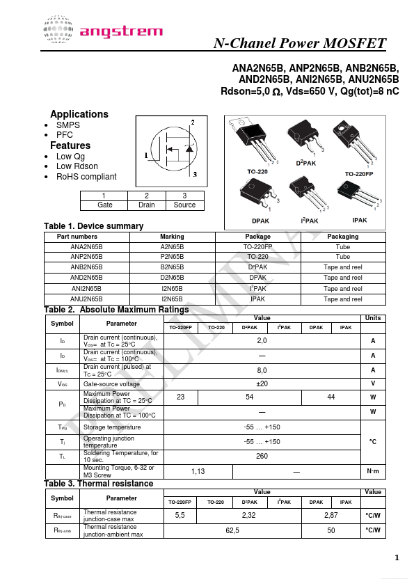
N-Chanel Power
MOSFET
ANA2N65B, ANP2N65B, ANB2N65B, AND2N65B, ANI2N65B, ANU2N65B Rdson=5,0 , Vds=650 V, Qg(tot)=8 nC Applications
SMPS PFC
Features
Low Qg Low Rdson RoHS compliant
1 Gate 2 Drain 3 Source
Table 1. Device summary
Part numbers ANA2N65B ANP2N65B ANB2N65B AND2N65B ANI2N65B ANU2N65B Marking A2N65B P2N65B B2N65B D2N65B I2N65B I2N65B Package TO-220FP TO-220 D²PAK DPAK I PAK IPAK Value
TO-220FP TO-220 D²PAK I2PAK DPAK IPAK
2
Packaging Tube Tube Tape and reel Tape and reel Tape and reel Tape and reel Units
Table 2. Absolute Maximum Ratings
Symbol ID ID IDM(1) VGS PD Parameter Drain current (continuous), VGS= at TC = 25°C Drain current (continuous), VGS= at TC = 100°C Drain current (pulsed) at TC = 25°C Gate-source
voltage Maximum Power Dissipation at TC = 25°C Maximum Power Dissipation at TC = 100°C Storage temperature Operating junction temperature Soldering Temperature, for 10 sec. Mounting Torque, 6-32 or M3 Screw
2,0 ― 8,0 ±20 23 54 ― -55 … +150 -55 … +150 260 1,13
Value
TO-220FP TO-220 D²PAK I PAK
2
A A A V
44
W W
Tstg Tj TL
°C
―
N·m Value
DPAK IPAK
Table 3. Thermal resistance
Symbol Rthj-case Rthj-amb Parameter Thermal resistance junction-case max Thermal resistance junction-ambient max
5,5 62,5
2,32
2,87 50
°C/W °C/W
1
Free Datasheet http://www.datasheet-pdf.com/
N-Chanel Power
MOSFET
Table 4. Electrical Characteristics of the
MOSFET
Symbol Parameter Min. Typ. Max. Units Conditions VGS = 0V, ID = 250μA ID = 250 μA, Referenced to 25°...