APT12057B2LL(G) APT12057LLL(G)
1200V 22A 0.570Ω
*G Denotes RoHS Compliant, Pb Free Terminal Finish.
POWER MOS 7 R MOSFE...
APT12057B2LL(G) APT12057LLL(G)
1200V 22A 0.570Ω
*G Denotes RoHS Compliant, Pb Free Terminal Finish.
POWER MOS 7 R
MOSFET
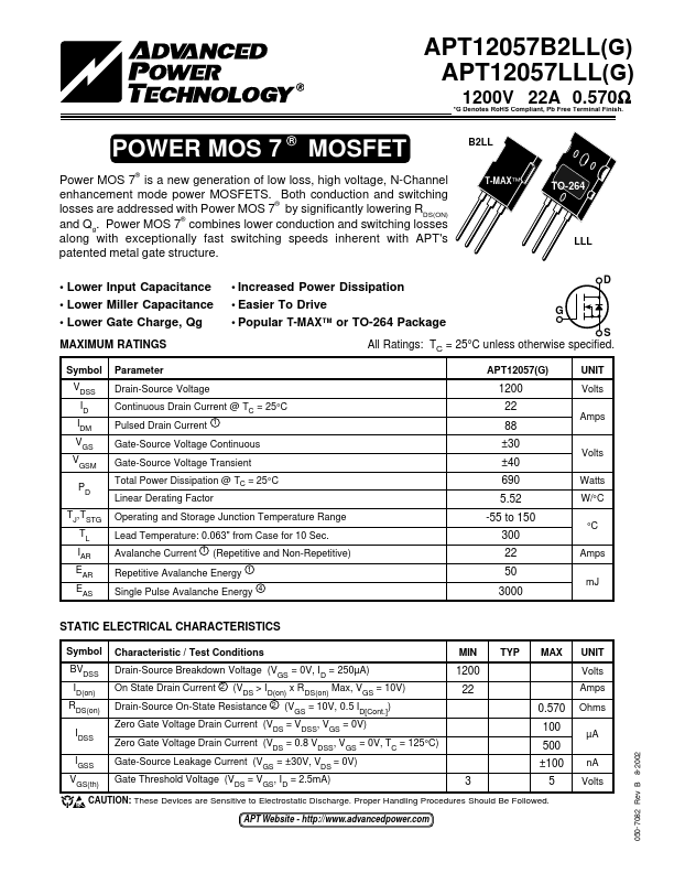
B2LL
Power MOS 7® is a new generation of low loss, high
voltage, N-Channel
enhancement mode power
MOSFETS. Both conduction and switching
losses are addressed and Qg. Power MOS
with Power MOS 7® by significantly lowering 7® combines lower conduction and switching
RDS(ON) losses
along with exceptionally fast switching speeds inherent with APT's
patented metal gate structure.
T-MAX™
TO-264
LLL
Lower Input Capacitance Lower Miller Capacitance Lower Gate Charge, Qg
MAXIMUM RATINGS
Increased Power Dissipation
D
Easier To Drive
G
Popular T-MAX™ or TO-264 Package
S
All Ratings: TC = 25°C unless otherwise specified.
Symbol VDSS ID IDM VGS VGSM
PD
TJ,TSTG TL IAR EAR EAS
Parameter Drain-Source
Voltage Continuous Drain Current @ TC = 25°C Pulsed Drain Current 1 Gate-Source
Voltage Continuous Gate-Source
Voltage Transient Total Power Dissipation @ TC = 25°C Linear Derating Factor
Operating and Storage Junction Temperature Range Lead Temperature: 0.063" from Case for 10 Sec. Avalanche Current 1 (Repetitive and Non-Repetitive) Repetitive Avalanche Energy 1 Single Pulse Avalanche Energy 4
APT12057(G) 1200 22 88 ±30 ±40 690 5.52
-55 to 150 300 22 50 3000
UNIT Volts Amps
Volts Watts W/°C
°C Amps
mJ
STATIC ELECTRICAL CHARACTERISTICS
Symbol BVDSS ID(on) RDS(on)
IDSS
IGSS VGS(th)
Characteristic / Test Conditions
Drain-Source Breakdown Volt...