www.DataSheet4U.com
TYPICAL PERFORMANCE CURVES ®
APT50GP60B2DQ2 APT50GP60B2DQ2G*
APT50GP60B2DQ2(G) 600V
*G Denotes R...
www.DataSheet4U.com
TYPICAL PERFORMANCE CURVES ®
APT50GP60B2DQ2 APT50GP60B2DQ2G*
APT50GP60B2DQ2(G) 600V
*G Denotes RoHS Compliant, Pb Free Terminal Finish.
POWER MOS 7 IGBT
®
(B2)
T-Max®
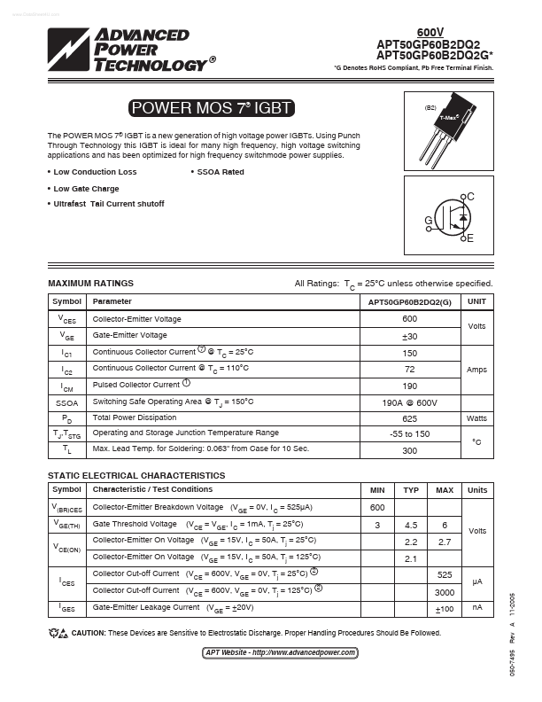
The POWER MOS 7® IGBT is a new generation of high
voltage power IGBTs. Using Punch Through Technology this IGBT is ideal for many high frequency, high
voltage switching applications and has been optimized for high frequency switchmode power supplies. Low Conduction Loss Low Gate Charge Ultrafast Tail Current shutoff SSOA Rated
C G E
MAXIMUM RATINGS
Symbol VCES VGE I C1 I C2 I CM SSOA PD TJ,TSTG TL Parameter Collector-Emitter
Voltage Gate-Emitter
Voltage Continuous Collector Current
7
All Ratings: TC = 25°C unless otherwise specified.
APT50GP60B2DQ2(G) UNIT Volts
600 ±30
@ TC = 25°C
150 72 190 190A @ 600V 625 -55 to 150 300
Watts °C Amps
Continuous Collector Current @ TC = 110°C Pulsed Collector Current
1
Switching Safe Operating Area @ TJ = 150°C Total Power Dissipation Operating and Storage Junction Temperature Range Max. Lead Temp. for Soldering: 0.063" from Case for 10 Sec.
STATIC ELECTRICAL CHARACTERISTICS
Symbol V(BR)CES VGE(TH) VCE(ON) Characteristic / Test Conditions Collector-Emitter Breakdown
Voltage (VGE = 0V, I C = 525µA) Gate Threshold
Voltage (VCE = VGE, I C = 1mA, Tj = 25°C) MIN TYP MAX Units
600 3 4.5 2.2 2.1 525
2
6 2.7
Collector-Emitter On
Voltage (VGE = 15V, I C = 50A, Tj = 25°C) Collector-Emitter On
Voltage (VGE = 15V, I C = 50A, Tj = 125°C) Collect...