n-channel JFETs designed for • • •
• VHF/UHF Amplifiers • Oscillators • Mixers
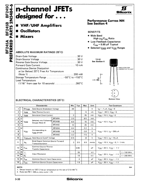
ABSOLUTE MAXIMUM RATINGS (25°C) Drain·Gat...
n-channel JFETs designed for
VHF/UHF
Amplifiers Oscillators Mixers
ABSOLUTE MAXIMUM RATINGS (25°C) Drain·Gate
Voltage ............................. 30 V Drain-Source
Voltage ........................... 30 V Reverse Gate-Source
Voltage...................... 30 V Forward Gate Current ......................... 10 mA Continuous Device Dissipation
at (or Below) 25°C Free Air Temperature (Note 1) ................................ 200 mW Storage Temperature Range ............ -55°C to +150°C Lead Temperature (1/16" from case for 10 seconds) ...............260°C
ELECTRICAL CHARACTERISTICS (25°C)
H
Billcanix
Performance Curves NH See Sedion 4
BENEFITS Wide Band
High Yfs/Ciss Ratio
Low Feedback Capacitance Crss = 0.85 pF Typical Selected IDSS and V GS Ranges
TO·92 See Section 6
.~:
INSULATED CASE INSENSITIVE TO LIGHT
sD
DOG
GC
SC Bottom View
Characteristic
-1 2 --;:-
I-=- S
!~ T
5A 1- T
I~ I
1---2.. C
8
Ig
1-
10
BVGSS IGSS iOSS
lOSS
Gate-Source Breakdown
Voltage
Gate Reverse Current
Saturation Drain Current
Selected Into Following Groups INote 21
BF245A BF245B BF245C
VGS
Corresponding to lOSS groups
BF245A BF245B BF245C
VGSloff) Gate·Source Cutoff
Voltage
11 gfs
1-0
12 V Crss
I- N
11413
A M
-1
g,s
I-I
15 C CISS
""16 Coss
Smail-Signal Common-Source Forward Transconductance Common-Source Reverse Transfer Capacitance
Input Resistance
Common·Source Input Capacitance Common-Source Output Capacitance
Min Typ -30
2 20 6.0 12 -{).4 16 -3.2 -{)5
...