2.5-V PHASE LOCK LOOP CLOCK DRIVER
CDCV857B, CDCV857BI 2.5ĆV PHASEĆLOCK LOOP CLOCK DRIVER
D Phase-Lock Loop Clock Driver for Double
Data-Rate Synchronous ...
Description
CDCV857B, CDCV857BI 2.5ĆV PHASEĆLOCK LOOP CLOCK DRIVER
D Phase-Lock Loop Clock Driver for Double
Data-Rate Synchronous DRAM Applications
D Spread Spectrum Clock Compatible D Operating Frequency: 60 MHz to 200 MHz D Low Jitter (cycle-cycle): ±50 ps D Low Static Phase Offset: ±50 ps D Low Jitter (Period): ±35 ps D Distributes One Differential Clock Input to
10 Differential Outputs
SCAS689 − FEBRUARY 2003
D Enters Low-Power Mode When No CLK
Input Signal Is Applied or PWRDWN Is Low
D Operates From Dual 2.5-V Supplies D Available in a 48-Pin TSSOP Package or
56-Ball MicroStar Junior BGA Package
D Consumes < 100-µA Quiescent Current D External Feedback Pins (FBIN, FBIN) Are
Used to Synchronize the Outputs to the Input Clocks
D Meets/Exceeds the Latest DDR JEDEC
Spec JESD82−1
description
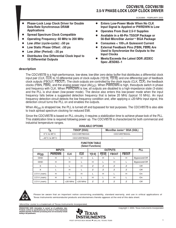
The CDCV857B is a high-performance, low-skew, low-jitter zero delay buffer that distributes a differential clock input pair (CLK, CLK) to 10 differential pairs of clock outputs (Y[0:9], Y[0:9]) and one differential pair of feedback clock outputs (FBOUT, FBOUT). The clock outputs are controlled by the clock inputs (CLK, CLK), the feedback clocks (FBIN, FBIN), and the analog power input (AVDD). When PWRDWN is high, theoutputs switch in phase and frequency with CLK. When PWRDWN is low, all outputs are disabled to a high-impedance state (3-state) and the PLL is shut down (low-power mode). The device also enters this low-power mode when the input frequency falls below a suggested detection frequency...
Similar Datasheet