DF005S THRU DF10S
MINIATURE GLASS PASSIVATED SINGLE-PHASE SURFACE MOUNT BRIDGE RECTIFIER
Reverse Voltage - 50 to 1000 Vo...
DF005S THRU DF10S
MINIATURE GLASS PASSIVATED SINGLE-PHASE SURFACE MOUNT BRIDGE RECTIFIER
Reverse
Voltage - 50 to 1000 Volts
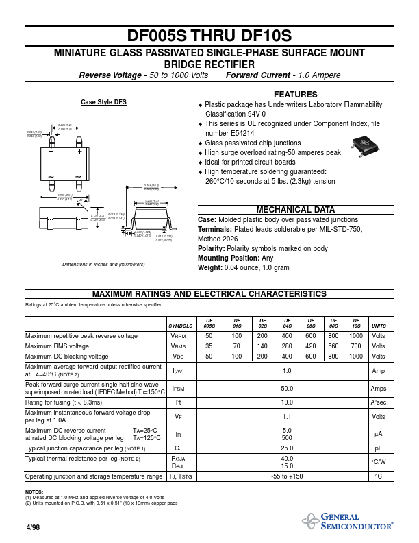
Case Style DFS
Forward Current - 1.0 Ampere
FEATURES
0.047 (1.20) 0.040 (1.02)
0.205 (5.2) 0.195 (5.0)
0.404 (10.3) 0.386 (9.80) 0.335 (8.51) 0.320 (8.13) 45o 0.255 (6.5) 0.245 (6.2)
♦ Plastic package has Underwriters Laboratory Flammability Classification 94V-0 ♦ This series is UL recognized under Component Index, file number E54214 ♦ Glass passivated chip junctions ♦ High surge overload rating-50 amperes peak ♦ Ideal for printed circuit boards ♦ High temperature soldering guaranteed: 260°C/10 seconds at 5 lbs. (2.3kg) tension
0.013 (0.330) 0.130 (3.3) 0.009 (0.241) 0.120 (3.05)
MECHANICAL DATA
0.060 (1.524) 0.040 (1.016)
0.013 (0.330) 0.003 (0.076)
Dimensions in inches and (millimeters)
Case: Molded plastic body over passivated junctions Terminals: Plated leads solderable per MIL-STD-750, Method 2026 Polarity: Polarity symbols marked on body Mounting Position: Any Weight: 0.04 ounce, 1.0 gram
MAXIMUM RATINGS AND ELECTRICAL CHARACTERISTICS
Ratings at 25°C ambient temperature unless otherwise specified.
SYMBOLS
DF 005S
DF 01S
DF 02S
DF 04S
DF 06S
DF 08S
DF 10S
UNITS
Maximum repetitive peak reverse
voltage Maximum RMS
voltage Maximum DC blocking
voltage Maximum average forward output rectified current at TA=40°C (NOTE 2) Peak forward surge current single half sine-wave superimposed on rated load (JEDEC Method) TJ=150°C Rating for fusi...