EcoSPARK) 3 Ignition IGBT
200 mJ, 400 V, N-Channel Ignition IGBT
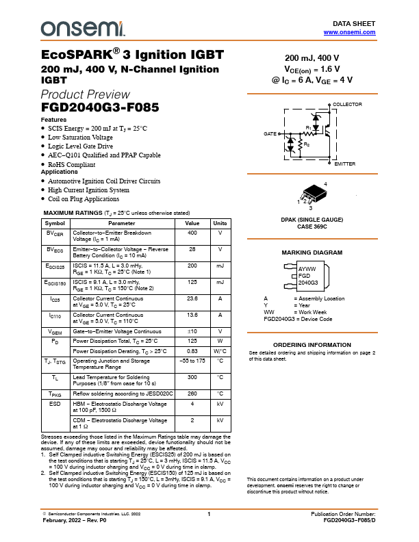
Product Preview FGD2040G3-F085
Features
• SCIS Energy =...
EcoSPARK) 3 Ignition IGBT
200 mJ, 400 V, N-Channel Ignition IGBT
Product Preview FGD2040G3-F085
Features
SCIS Energy = 200 mJ at TJ = 25°C Low Saturation
Voltage Logic Level Gate Drive AEC−Q101 Qualified and PPAP Capable RoHS Compliant
Applications
Automotive Ignition Coil Driver Circuits High Current Ignition System Coil on Plug Applications
MAXIMUM RATINGS (TJ = 25°C unless otherwise stated)
Symbol
Parameter
Value
Units
BVCER BVECS ESCIS25 ESCIS150
IC25 IC110 VGEM PD
TJ, TSTG
Collector−to−Emitter Breakdown
Voltage (IC = 1 mA)
Emitter−to−Collector
Voltage − Reverse Battery Condition (IC = 10 mA)
ISCIS = 11.5 A, L = 3.0 mHy, RGE = 1 KW, TC = 25°C (Note 1)
ISCIS = 9.1 A, L = 3.0 mHy, RGE = 1 KW, TC = 150°C (Note 2)
Collector Current Continuous at VGE = 5.0 V, TC = 25°C
Collector Current Continuous at VGE = 5.0 V, TC = 110°C
Gate−to−Emitter
Voltage Continuous
Power Dissipation Total, TC = 25°C
Power Dissipation Derating, TC > 25°C
Operating Junction and Storage Temperature Range
400
V
28
V
200
mJ
125
mJ
23.6
A
13.6
A
±10 125 0.83 −55 to 175
V W W/°C °C
TL
Lead Temperature for Soldering
Purposes (1/8″ from case for 10 s)
300
°C
TPKG Reflow soldering according to JESD020C
260
°C
ESD
HBM − Electrostatic Discharge
Voltage at 100 pF, 1500 W
4
kV
CDM − Electrostatic Discharge
Voltage
2
kV
at 1 W
Stresses exceeding those listed in the Maximum Ratings table may damage the device. If any of these limits are exceeded, device functiona...