4-Pin DIP Phototransistor Optocouplers
4-Pin DIP Phototransistor Optocouplers
FOD814, FOD817
Introduction or Description The FOD814 consists of two gallium ars...
Description
4-Pin DIP Phototransistor Optocouplers
FOD814, FOD817
Introduction or Description The FOD814 consists of two gallium arsenide infrared emitting
diodes, connected in inverse parallel, driving a silicon phototransistor output in a 4−pin dual in−line package. The FOD817 Series consists of a gallium arsenide infrared emitting diode driving a silicon phototransistor in a 4−pin dual in−line package.
Features
AC Input Response (FOD814) Current Transfer Ratio in Selected Groups
♦ FOD814: 20–300% ♦ FOD814A: 50–150% ♦ FOD817: 50–600% ♦ FOD817A: 80–160% ♦ FOD817B: 130–260% ♦ FOD817C: 200–400% ♦ FOD817D: 300–600%
Minimum BVCEO of 70 V Guaranteed Safety and Regulatory Approvals
♦ UL1577, 5,000 VACRMS for 1 Minute ♦ DIN EN/IEC60747−5−5
This Device is Pb−Free
Typical Applications
FOD814 Series
♦ AC Line Monitor ♦ Unknown Polarity DC Sensor ♦ Telephone Line Interface
FOD817 Series
♦ Power Supply Regulators ♦ Digital Logic Inputs ♦ Microprocessor Inputs
DATA SHEET www.onsemi.com
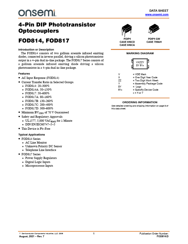
PDIP4 CASE 646CD CASE 646CA
PDIP4 GW CASE 709AH
MARKING DIAGRAM
VXZZY $Y 81x
V
= VDE Mark
X
= One Digit Year Code
ZZ
= Two Digit Work Week
Y
= Assembly Package Code
$Y
= Logo
81x
= Specific Device Code
x = 4 or 7
ORDERING INFORMATION
See detailed ordering and shipping information on page 8 of this data sheet.
© Semiconductor Components Industries, LLC, 2006
1
August, 2021 − Rev. 7
Publication Order Number: FOD814/D
FOD814, FOD817
FUNCTIONAL BLOCK DIAGRAM
Anode, Cathode 1
4 Colle...
Similar Datasheet