HGTG20N100D2
May 1995
20A, 1000V N-Channel IGBT
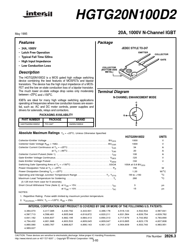
Package
JEDEC STYLE TO-247
EMITTER COLLECTOR GATE
Features
• 34A, 1000...
HGTG20N100D2
May 1995
20A, 1000V N-Channel IGBT
Package
JEDEC STYLE TO-247
EMITTER COLLECTOR GATE
Features
34A, 1000V Latch Free Operation Typical Fall Time 520ns High Input Impedance Low Conduction Loss
Description
The HGTG20N100D2 is a MOS gated high
voltage switching device combining the best features of
MOSFETs and bipolar transistors. The device has the high input impedance of a
MOSFET and the low on-state conduction loss of a bipolar transistor. The much lower on-state
voltage drop varies only moderately between +25oC and +150oC. IGBTs are ideal for many high
voltage switching applications operating at frequencies where low conduction losses are essential, such as: AC and DC motor controls, power supplies and drivers for solenoids, relays and contactors.
PACKAGING AVAILABILITY PART NUMBER HGTG20N100D2 PACKAGE TO-247 BRAND G20N100D2
COLLECTOR (BOTTOM SIDE METAL)
Terminal Diagram
N-CHANNEL ENHANCEMENT MODE
C
G
E
Absolute Maximum Ratings
TC = +25oC, Unless Otherwise Specified HGTG20N100D2 1000 1000 34 20 100 ±20 ±30 100A at 0.8 BVCES 150 1.20 -55 to +150 260 3 15 UNITS V V A A A V V W W/oC oC oC µs µs
Collector-Emitter
Voltage . . . . . . . . . . . . . . . . . . . . . . . . . . . . . . . . . . . . . . . . . . . . BVCES Collector-Gate
Voltage RGE = 1MΩ . . . . . . . . . . . . . . . . . . . . . . . . . . . . . . . . . . . . BVCGR Collector Current Continuous at TC = +25oC . . . . . . . . . . . . . . . . . . . . . . . . . . . . . . . IC25 at TC = +90oC . . ...