www.DataSheet4U.com
ISSUED DATE :2003/05/15 REVISED DATE :2004/11/10B
G431
Description
Adjustable Shunt Regulator
Pac...
www.DataSheet4U.com
ISSUED DATE :2003/05/15 REVISED DATE :2004/11/10B
G431
Description
Adjustable Shunt Regulator
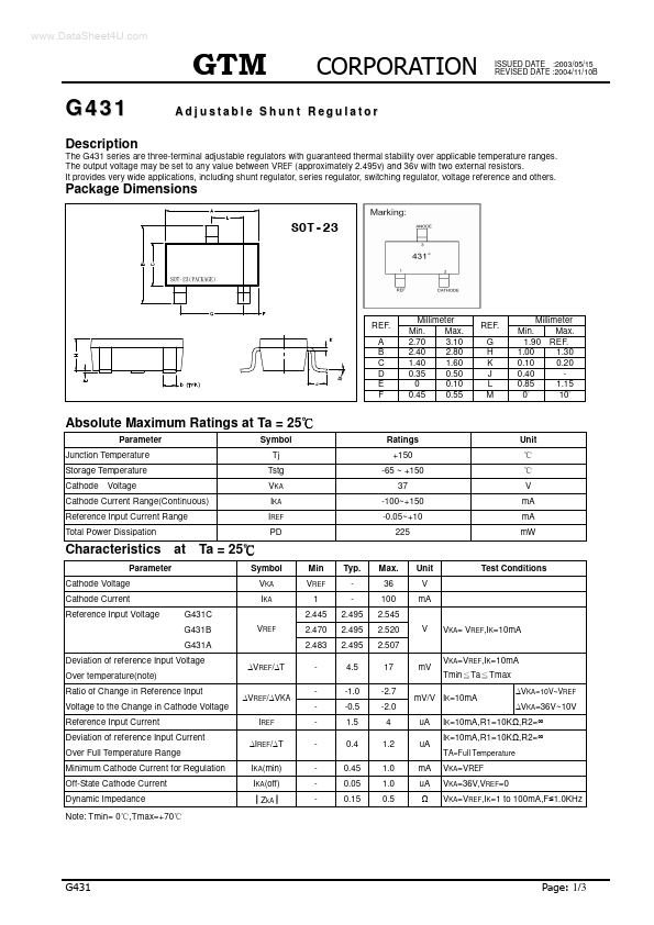
Package Dimensions
The G431 series are three-terminal adjustable regulators with guaranteed thermal stability over applicable temperature ranges. The output
voltage may be set to any value between VREF (approximately 2.495v) and 36v with two external resistors. It provides very wide applications, including shunt regulator, series regulator, switching regulator,
voltage reference and others.
REF. A B C D E F
Millimeter Min. Max. 2.70 3.10 2.40 2.80 1.40 1.60 0.35 0.50 0 0.10 0.45 0.55
REF. G H K J L M
Millimeter Min. Max. 1.90 REF. 1.00 1.30 0.10 0.20 0.40 0.85 1.15 10 0
Absolute Maximum Ratings at Ta = 25
Parameter Junction Temperature Storage Temperature Cathode
Voltage Cathode Current Range(Continuous) Reference Input Current Range Total Power Dissipation Symbol Tj Tstg VKA IKA IREF PD Ratings +150 -65 ~ +150 37 -100~+150 -0.05~+10 225 V mA mA mW Unit
Characteristics
Parameter Cathode
Voltage Cathode Current Reference Input
Voltage
at Ta = 25
Symbol VKA IKA G431C G431B G431A VREF Min VREF 1 2.445 2.470 2.483 VREF/ T VREF/ VKA IREF IREF/ T IKA(min) IKA(off) ZkA Typ. 2.495 2.495 2.495 4.5 -1.0 -0.5 1.5 0.4 0.45 0.05 0.15 Max. 36 100 2.545 2.520 2.507 17 -2.7 -2.0 4 1.2 1.0 1.0 0.5 mV VKA=VREF,IK=10mA Tmin Ta Tmax VKA=10V~VREF VKA=36V~10V V VKA= VREF,IK=10mA Unit V mA Test Conditions
Deviation of reference Input
Voltage Over temperature(note) Ratio of C...