Technical Data 4449
Effective July 2017 Supersedes June 2012
HCM1103
High current power inductors
Product features • ...
Technical Data 4449
Effective July 2017 Supersedes June 2012
HCM1103
High current power inductors
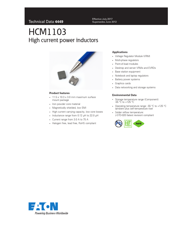
Product features 11.5 x 10.3 x 3.0 mm maximum surface
mount package Iron powder core material Magnetically shielded, low EMI High current carrying capacity, low core losses Inductance range from 0.12 µH to 22.0 µH Current range from 3.0 A to 75 A Halogen free, lead free, RoHS compliant
Applications
Voltage Regulator Module (VRM) Multi-phase regulators Point-of-load modules Desktop and server VRMs and EVRDs Base station equipment Notebook and laptop regulators Battery power systems Graphics cards Data networking and storage systems
Environmental Data Storage temperature range (Component):
-55 °C to +125 °C Operating temperature range: -55 °C to +125 °C
(ambient plus self-temperature rise) Solder reflow temperature:
J-STD-020 (latest revision) compliant
Pb HFHALOGEN FREE
Technical Data 4449
Effective July ...