v03.0507
Typical Applications
Low noise MMIC VCO w/Buffer Amplifier for: • Wireless Local Loop (WLL) • VSAT & Microwave ...
v03.0507
Typical Applications
Low noise MMIC VCO w/Buffer Amplifier for: Wireless Local Loop (WLL) VSAT & Microwave Radio Test Equipment & Industrial Controls Military
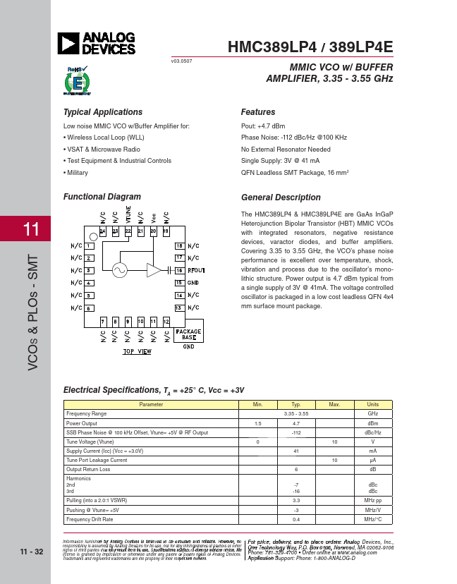
Functional Diagram
11
HMC389LP4 / 389LP4E
MMIC VCO w/ BUFFER AMPLIFIER, 3.35 - 3.55 GHz
Features
Pout: +4.7 dBm Phase Noise: -112 dBc/Hz @100 KHz No External Resonator Needed Single Supply: 3V @ 41 mA QFN Leadless SMT Package, 16 mm2
General Description
The HMC389LP4 & HMC389LP4E are GaAs InGaP Heterojunction Bipolar Transistor (HBT) MMIC VCOs with integrated resonators, negative resistance devices, varactor diodes, and buffer
amplifiers. Covering 3.35 to 3.55 GHz, the VCO’s phase noise performance is excellent over temperature, shock, vibration and process due to the oscillator’s monolithic structure. Power output is 4.7 dBm typical from a single supply of 3V @ 41mA. The
voltage controlled oscillator is packaged in a low cost leadless QFN 4x4 mm surface mount package.
VCOS & PLOs - SMT
11 - 32
Electrical Specifications, TA = +25° C, Vcc = +3V
Parameter
Min.
Frequency Range
Power Output
1.5
SSB Phase Noise @ 100 kHz Offset, Vtune= +5V @ RF Output
Tune
Voltage (Vtune)
0
Supply Current (Icc) (Vcc = +3.0V)
Tune Port Leakage Current
Output Return Loss
Harmonics 2nd 3rd
Pulling (into a 2.0:1 VSWR)
Pushing @ Vtune= +5V
Frequency Drift Rate
Typ. 3.35 - 3.55
4.7 -112
41
6
-7 -16 3.3 -3 0.4
Max.
10 10
Units GHz dBm dBc/Hz
V mA μA dB
dBc dBc MHz pp MHz/V MHz/°C
Information furnisheFd obyr A...