HVM187S
Silicon Epitaxial Planar PIN Diode for High Frequency Attenuator
ADE-208-055C (Z) Rev. 3 Jun. 1993 Features
• L...
HVM187S
Silicon Epitaxial Planar PIN Diode for High Frequency Attenuator
ADE-208-055C (Z) Rev. 3 Jun. 1993 Features
Low forward resistance. (rf = 5.5 max) MPAK package is suitable for high density surface mounting and high speed assembly.
Ordering Information
Type No. HVM187S Laser Mark H3 Package Code MPAK
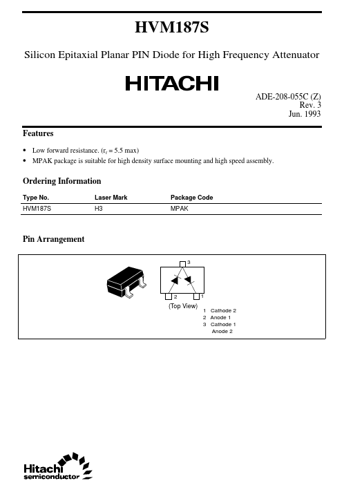
Pin Arrangement
3
2
1
(Top View)
1 Cathode 2 2 Anode 1 3 Cathode 1 Anode 2
HVM187S
Absolute Maximum Ratings (Ta = 25°C)
Item Reverse
voltage Forward current Power dissipation Junction temperature Storage temperature Note: Per one device Symbol VR IF Pd* Tj Tstg Value 60 50 100 125 –55 to +125 Unit V mA mW °C °C
Electrical Characteristics (Ta = 25°C)
Item Forward
voltage Reverse current Capacitance Forward resistance ESD-Capability Symbol VF IR C rf — Min — — — 3.5 200 Typ — — — — — Max 1.0 100 2.4 5.5 — Unit V nA pF Ω V Test Condition I F = 10mA VR = 60V VR = 0V, f = 1MHz I F = 10mA, f = 100MHz *C = 200pF, Both forward and reverse direction 1 pulse.
Note: Failure criterion; IR ≥ 100nA at VR = 60V
10
–2
10
–4
Forward current I F (A)
10–6
10
–8
10–10
10
–12
0
0.2
0.4
0.6
0.8
1.0
Forward
voltage VF (V)
Fig.1 Forward current Vs. Forward
voltage
2
HVM187S
10
–8
Reverse current I R (A)
10
–9
10
–10
10
–11
10
–12
0
60 20 80 40 Reverse
voltage VR (V)
100
Fig.2 Reverse current Vs. Reverse
voltage
f = 1MHz
10 Capacitance C (pF)
1.0
10
–1
1.0
10 Reverse
voltage VR (V)
10
2
Fig.3 Capacitance Vs. Reverse
voltage
3
HVM187S
10
4...