www.DataSheet4U.com
IQXO-70, -71
ISSUE 7; 13 SEPTEMBER 1999 Delivery Options
■
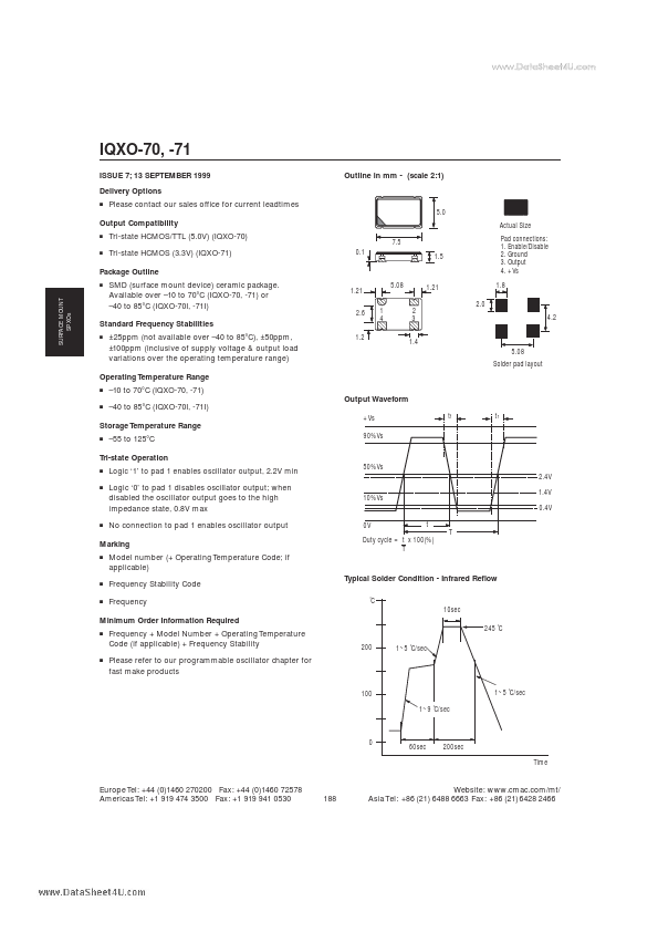
Outline in mm - (scale 2:1)
Please con...
www.DataSheet4U.com
IQXO-70, -71
ISSUE 7; 13 SEPTEMBER 1999 Delivery Options
■
Outline in mm - (scale 2:1)
Please contact our sales office for current leadtimes
5.0
Output Compatibility
■
Actual Size
Tri-state H
CMOS/TTL (5.0V) (IQXO-70) Tri-state H
CMOS (3.3V) (IQXO-71)
0.1
7.5 1.5
■
Package Outline
■
Pad connections: 1. Enable/Disable 2. Ground 3. Output 4. +Vs 1.8
2.0
SURFACE MOUNT SPXOs
SMD (surface mount device) ceramic package. Available over –10 to 70°C (IQXO-70, -71) or –40 to 85°C (IQXO-70I, -71I)
1.21 2.6 1 4
5.08 2 3 1.4
1.21
Standard Frequency Stabilities
■
4.2
±25ppm (not available over –40 to 85°C), ±50ppm, ±100ppm (inclusive of supply
voltage & output load variations over the operating temperature range)
1.2
5.08
Solder pad layout
Operating Temperature Range
■
–10 to 70°C (IQXO-70, -71) Output Waveform –40 to 85°C (IQXO-70I, -71I)
tf tr
■
+Vs
Storage Temperature Range
■
–55 to 125°C
90%Vs
Tri-state Operation
■
Logic ‘1’ to pad 1 enables oscillator output, 2.2V min Logic ‘0’ to pad 1 disables oscillator output; when disabled the oscillator output goes to the high impedance state, 0.8V max No connection to pad 1 enables oscillator output
50%Vs 2.4V 1.4V 0.4V
0V t T
■
10%Vs
■
Marking
■
Duty cycle = t x 100(%) T
Model number (+ Operating Temperature Code; if applicable) Frequency Stability Code Frequency Typical Solder Condition - Infrared Reflow
˚C 10sec
■
■
Minimum Order Information Required
■
Frequency + Model Number + Operat...