High Voltage IGBT with Diode IXGP 20N120B IXGP 20N120BD1
Preliminary Data Sheet
VCES IC25 VCE(sat)
tfi(typ)
= 1200 V =...
High
Voltage IGBT with Diode IXGP 20N120B IXGP 20N120BD1
Preliminary Data Sheet
VCES IC25 VCE(sat)
tfi(typ)
= 1200 V = 40 A = 3.4 V = 160 ns
Symbol
Test Conditions
VCES VCGR
VGES VGEM
IC25 IC110 ICM
SSOA (RBSOA)
TJ = 25°C to 150°C TJ = 25°C to 150°C; RGE = 1 MΩ Continuous Transient
TC = 25°C TC = 110°C TC = 25°C, 1 ms VGE = 15 V, TJ = 125°C, RG = 10 Ω Clamped inductive load
PC TC = 25°C
TJ TJM Tstg
Md Mounting torque (M3.5 screw)
Maximum lead temperature for soldering 1.6 mm (0.062 in.) from case for 10 s
Maximum tab temperature soldering SMD devices for 10s
Weight
D1 Maximum Ratings
1200 1200
V V
±20 V ±30 V
40 A 20 A 100 A
ICM = 40 @0.8 VCES
190
A W
-55 ... +150 150
-55 ... +150
°C °C °C
0.55/5 Nm/lb.in.
300 °C
260 °C
4g
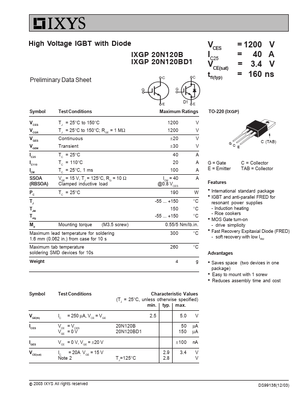
TO-220 (IXGP)
GC E
C (TAB)
G = Gate E = Emitter
C = Collector TAB = Collector
Features
z International standard package z IGBT and anti-parallel FRED for
resonant power supplies - Induction heating - Rice cookers z MOS Gate turn-on - drive simplicity z Fast Recovery Expitaxial Diode (FRED) - soft recovery with low IRM
Advantages
z Saves space (two devices in one package)
z Easy to mount with 1 screw z Reduces assembly time and cost
Symbol
VGE(th) ICES IGES VCE(sat)
Test Conditions
IC = 250 µA, VCE = VGE VCE = VCES VGE = 0 V VCE = 0 V, VGE = ±20 V IC = 20A, VGE = 15 V Note 2
Characteristic Values (TJ = 25°C, unless otherwise specified)
min. typ. max.
20N120B 20N120BD1
2.5
5.0 V
50 µA 150 µA
TJ=125°C
±100 nA
2.9 3.4 V 2.8 ...