Advanced Technical Information
High Voltage MOSFET
N-Channel Enhancement Mode Avalanche Energy Rated
IXTA 1N100 IXTP 1...
Advanced Technical Information
High
Voltage MOSFET
N-Channel Enhancement Mode Avalanche Energy Rated
IXTA 1N100 IXTP 1N100
VDSS ID25
RDS(on)
= 1000 V = 1.5 A = 11 Ω
Symbol VDSS VDGR VGS VGSM ID25 IDM IAR EAR EAS dv/dt PD TJ TJM Tstg Md Weight
Test Conditions TJ = 25°C to 150°C TJ = 25°C to 150°C; RGS = 1 MΩ Continuous Transient TC = 25°C TC = 25°C, pulse width limited by TJM
Maximum Ratings 1000 1000 ±20 ±30 1.5 6 1.5 V V V V A A A mJ mJ V/ns W °C °C °C
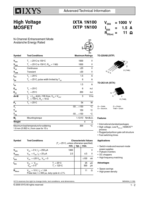
TO-220AB (IXTP)
GD
D (TAB) S
TO-263 AA (IXTA)
TC = 25°C TC = 25°C IS ≤ IDM, di/dt ≤ 100 A/µs, VDD ≤ VDSS, TJ ≤ 150°C, RG = 18 Ω TC = 25°C
6 200 3 54 -55 ... +150 150 -55 ... +150
G S D (TAB)
G = Gate, S = Source,
D = Drain, TAB = Drain
Mounting torque
1.13/10 Nm/lb.in. 4 300 g °C
Features
Maximum lead temperature for soldering 1.6 mm (0.062 in.) from case for 10 s
International standard packages High
voltage, Low RDS (on) HDMOSTM
process
Rugged polysilicon gate cell structure Fast switching times
Symbol Test Conditions Characteristic Values (TJ = 25°C, unless otherwise specified) min. typ. max. 1000 2.5 4.5 ±100 TJ = 25°C TJ = 125°C 25 500 11 V V nA µA µA Ω Applications
Switch-mode and resonant-mode
power supplies
VDSS VGS(th) IGSS IDSS RDS(on)
VGS = 0 V, ID = 250 µA VDS = VGS, ID = 25 µA VGS = ±20 VDC, VDS = 0 VDS = VDSS VGS = 0 V
Flyback inverters DC choppers High frequency matching
Advantages
VGS = 10 V, ID = 1.0A Pulse test, t ≤ 300 µs, duty cycle d ≤ 2 %
Space savings High p...