www.DataSheet4U.com
MAPRST0912-350 AVIONICS PULSED POWER TRANSISTOR
350 Watts, 960 - 1215 MHz, 10μs Pulse Width, 10% Du...
www.DataSheet4U.com
MAPRST0912-350 AVIONICS PULSED POWER TRANSISTOR
350 Watts, 960 - 1215 MHz, 10μs Pulse Width, 10% Duty Cycle
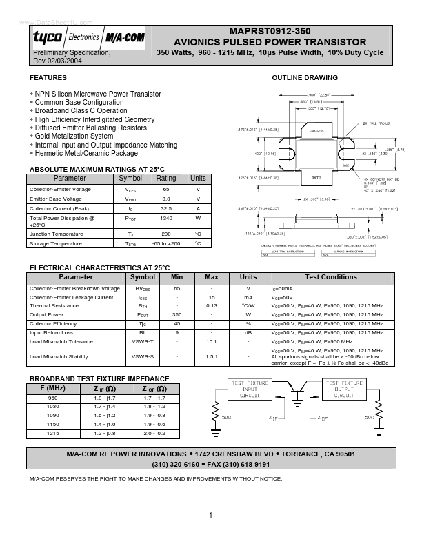
OUTLINE DRAWING
Preliminary Specification, Rev 02/03/2004 FEATURES
∗ NPN Silicon Microwave Power Transistor ∗ Common Base Configuration ∗ Broadband Class C Operation ∗ High Efficiency Interdigitated Geometry ∗ Diffused Emitter Ballasting Resistors ∗ Gold Metalization System ∗ Internal Input and Output Impedance Matching ∗ Hermetic Metal/Ceramic Package ABSOLUTE MAXIMUM RATINGS AT 25°C Parameter Symbol Rating
Collector-Emitter
Voltage Emitter-Base
Voltage Collector Current (Peak) Total Power Dissipation @ +25°C Junction Temperature Storage Temperature VCES VEBO IC PTOT TJ TSTG 65 3.0 32.5 1340 200 -65 to +200
Units
V V A W °C °C
ELECTRICAL CHARACTERISTICS AT 25°C Parameter Symbol Min
Collector-Emitter Breakdown
Voltage Collector-Emitter Leakage Current Thermal Resistance Output Power Collector Efficiency Input Return Loss Load Mismatch Tolerance Load Mismatch Stability BVCES ICES RTH POUT 65 350 45 9 -
Max
15 0.13 10:1 1.5:1
Units
V mA °C/W W % dB IC=50mA VCE=50V
Test Conditions
VCC=50 V, PIN=40 W, F=960, 1090, 1215 MHz VCC=50 V, PIN=40 W, F=960, 1090, 1215 MHz VCC=50 V, PIN=40 W, F=960, 1090, 1215 MHz VCC=50 V, PIN=40 W, F=960, 1090, 1215 MHz VCC=50 V, PIN=40 W, F=960 MHz VCC=50 V, PIN=40 W, F=960, 1090, 1215 MHz All spurious signals shall be < -60dBc below carrier, except F = Fo ± ½ Fo shall be < -40dBc
ηC
RL VSWR-T VSWR-S
BROADBAND TEST ...