MOTOROLA
SEMICONDUCTOR TECHNICAL DATA
Order this document by MC145146–2/D
MC145146-2 4-Bit Data Bus Input PLL Frequen...
MOTOROLA
SEMICONDUCTOR TECHNICAL DATA
Order this document by MC145146–2/D
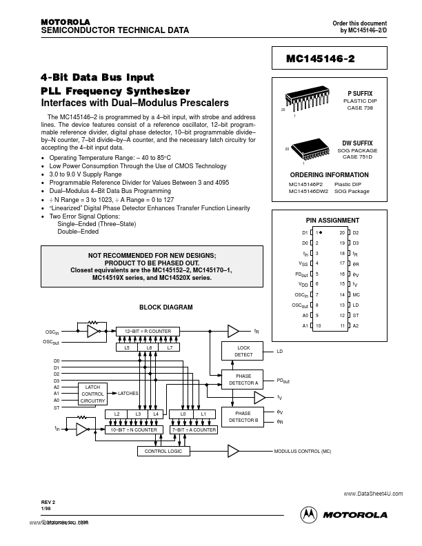
MC145146-2 4-Bit Data Bus Input PLL Frequency Synthesizer Interfaces with Dual–Modulus Prescalers
The MC145146–2 is programmed by a 4–bit input, with strobe and address lines. The device features consist of a reference oscillator, 12–bit programmable reference divider, digital phase detector, 10–bit programmable divide– by–N counter, 7–bit divide–by–A counter, and the necessary latch circuitry for accepting the 4–bit input data. Operating Temperature Range: – 40 to 85°C Low Power Consumption Through the Use of
CMOS Technology 3.0 to 9.0 V Supply Range Programmable Reference Divider for Values Between 3 and 4095 Dual–Modulus 4–Bit Data Bus Programming ÷ N Range = 3 to 1023, ÷ A Range = 0 to 127 “Linearized” Digital Phase Detector Enhances Transfer Function Linearity Two Error Signal Options: Single–Ended (Three–State) Double–Ended
20 1
P SUFFIX PLASTIC DIP CASE 738
20
DW SUFFIX SOG PACKAGE CASE 751D
1
ORDERING INFORMATION
MC145146P2 MC145146DW2 Plastic DIP SOG Package
PIN ASSIGNMENT
D1 D0 1 2 3 4 5 6 7 8 9 10 20 19 18 17 16 15 14 13 12 11 D2 D3 fR φR φV fV MC LD ST A2
NOT RECOMMENDED FOR NEW DESIGNS; PRODUCT TO BE PHASED OUT. Closest equivalents are the MC145152–2, MC145170–1, MC14519X series, and MC14520X series.
fin VSS PDout VDD OSCin
BLOCK DIAGRAM
OSCout A0
OSCin OSCout D0 D1 D2 D3 A2 A1 A0 ST
12–BIT ÷ R COUNTER L5 L6 L7 LOCK DETECT
fR
A1
LD
LATCH CONTROL CIRCUITRY
...