MOTOROLA
The RF Line
SEMICONDUCTOR TECHNICAL DATA
Order this document by MHW5222A/D
450 MHz CATV Amplifier
. . . desi...
MOTOROLA
The RF Line
SEMICONDUCTOR TECHNICAL DATA
Order this document by MHW5222A/D
450 MHz CATV Amplifier
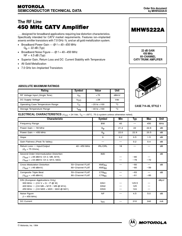
. . . designed for broadband applications requiring low distortion characteristics. Specifically intended for CATV market requirements. Features ion–implanted arsenic emitter transistors with 7.0 GHz fT, and an all gold metallization system. Broadband Power Gain @ f = 40 – 450 MHz Gp = 22 dB (Typ) Broadband Noise Figure @ f = 40 – 450 MHz NF = 4.5 dB (Typ) Superior Gain, Return Loss and DC Current Stability with Temperature All Gold Metallization 7.0 GHz Ion–Implanted Transistors
MHW5222A
22 dB GAIN 450 MHz 60–CHANNEL CATV TRUNK AMPLIFIER
ABSOLUTE MAXIMUM RATINGS
Rating RF
Voltage Input (Single Tone) DC Supply
Voltage Operating Case Temperature Range Storage Temperature Range Symbol Vin VCC TC Tstg Value + 70 + 28 – 20 to +100 – 40 to +100 Unit dBmV Vdc °C °C CASE 714–06, STYLE 1
ELECTRICAL CHARACTERISTICS (VCC = 24 Vdc, TC = +30°C, 75 Ω system unless otherwise noted)
Characteristic Frequency Range Power Gain — 50 MHz Power Gain — 450 MHz Slope Gain Flatness (Peak To Valley) Return Loss — Input/Output (Zo = 75 Ohms) Second Order Intermodulation Distortion (Vout = + 46 dBmV, Ch 2, M6, M15) (Vout = + 44 dBmV, Ch 2, M13, M22) Cross Modulation Distortion (Vout = + 46 dBmV) Composite Triple Beat (Vout = + 46 dBmV) DIN (European Applications Only) 300 MHz — (CH V + Q – P @ W) 400 MHz — (CH M8 + M15 – M9 @ M14) 450 MHz — (CH M20 + M23 – M22 @ M21) Noise Figu...