®
MJD31B/31C MJD32B/32C
COMPLEMENTARY SILICON POWER TRANSISTORS
s
s
s
STMicroelectronics PREFERRED SALESTYPES SURFA...
®
MJD31B/31C MJD32B/32C
COMPLEMENTARY SILICON POWER TRANSISTORS
s
s
s
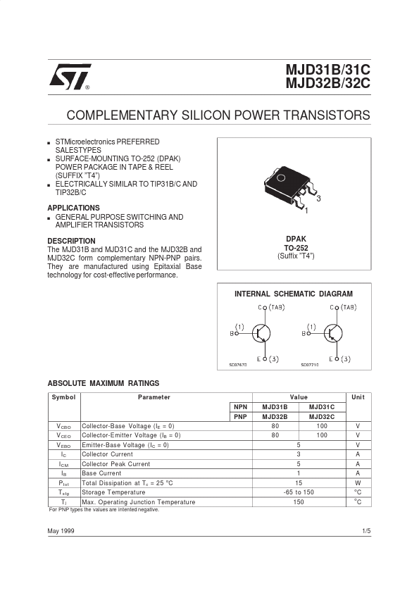
STMicroelectronics PREFERRED SALESTYPES SURFACE-MOUNTING TO-252 (DPAK) POWER PACKAGE IN TAPE & REEL (SUFFIX ”T4”) ELECTRICALLY SIMILAR TO TIP31B/C AND TIP32B/C
3 1
APPLICATIONS s GENERAL PURPOSE SWITCHING AND AMPLIFIER TRANSISTORS DESCRIPTION The MJD31B and MJD31C and the MJD32B and MJD32C form complementary NPN-PNP pairs. They are manufactured using Epitaxial Base technology for cost-effective performance.
DPAK TO-252 (Suffix ”T4”)
INTERNAL SCHEMATIC DIAGRAM
ABSOLUTE MAXIMUM RATINGS
Symbol Parameter NPN PNP V CBO V CEO V EBO IC I CM IB P t ot T stg Tj Collector-Base
Voltage (IE = 0) Collector-Emitter
Voltage (IB = 0) Emitter-Base
Voltage (IC = 0) Collector Current Collector Peak Current Base Current Total Dissipation at Tc = 25 C Storage T emperature Max. O perating Junction Temperature
o
Value MJD31B MJD32B 80 80 5 3 5 1 15 -65 to 150 150 MJD31C MJD32C 100 100
Uni t
V V V A A A W
o o
C C
For PNP types the values are intented negative.
May 1999
1/5
MJD31B/31C - MJD32B/32C
THERMAL DATA
R t hj-ca se R t hj- amb Thermal Resistance Junction-case Thermal Resistance Junction-ambient Max Max 8.33 100
o o
C/W C/W
ELECTRICAL CHARACTERISTICS (Tcase = 25 oC unless otherwise specified)
Symb ol I CES I CEO I EBO V CEO(sus) Parameter Collector Cut-off Current (V BE = 0) Collector Cut-off Current (I B = 0) Emitter Cut-off Current (I C = 0) Collector-Emitter Sustaining
Voltage Collector-Emitter Saturat...