MOTOROLA
SEMICONDUCTOR TECHNICAL DATA
Order this document by MRF19125/D
The RF Sub–Micron MOSFET Line
www.DataSheet4U...
MOTOROLA
SEMICONDUCTOR TECHNICAL DATA
Order this document by MRF19125/D
The RF Sub–Micron
MOSFET Line
www.DataSheet4U.com
RF Power Field Effect Transistors
N–Channel Enhancement–Mode Lateral
MOSFETs
Designed for PCN and PCS base station applications with frequencies from 1.9 to 2.0 GHz. Suitable for TDMA, CDMA and multicarrier amplifier applications. Typical 2–Carrier N–CDMA Performance for VDD = 26 Volts, IDQ = 1300 mA, f1 = 1958.75 MHz, f2 = 1961.25 MHz IS–95 CDMA (Pilot, Sync, Paging, Traffic Codes 8 Through 13) 1.2288 MHz Channel Bandwidth Carrier. Adjacent Channels Measured over a 30 kHz Bandwidth at f1 –885 kHz and f2 +885 kHz. Distortion Products Measured over 1.2288 MHz Bandwidth at f1 –2.5 MHz and f2 +2.5 MHz. Peak/Avg. = 9.8 dB @ 0.01% Probability on CCDF. Output Power — 24 Watts Avg. Power Gain — 13.6 dB Efficiency — 22% ACPR — –51 dB IM3 — –37.0 dBc Internally Matched, Controlled Q, for Ease of Use High Gain, High Efficiency and High Linearity Integrated ESD Protection Designed for Maximum Gain and Insertion Phase Flatness Capable of Handling 5:1 VSWR, @ 26 Vdc, 1990 MHz, 125 Watts (CW) Output Power Excellent Thermal Stability Characterized with Series Equivalent Large–Signal Impedance Parameters Available in Tape and Reel. R3 Suffix = 250 Units per 56 mm, 13 inch Reel.
MRF19125 MRF19125S MRF19125SR3
1990 MHz, 125 W, 26 V LATERAL N–CHANNEL RF POWER
MOSFETs
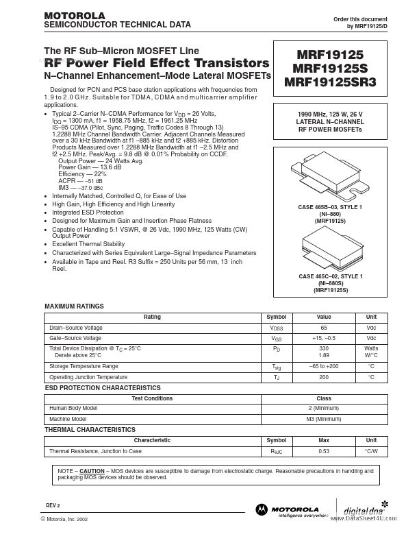
CASE 465B–03, STYLE 1 (NI–880) (MRF19125)
CASE 465C–02, STYLE 1 (NI–880S) (MRF19125...