NJM13775
DUAL STEPPER MOTOR DRIVER
GENERAL DESCRIPTION The NJM13775 is a switch-mode (chopper), constant
current dri...
NJM13775
DUAL STEPPER MOTOR DRIVER
GENERAL DESCRIPTION The NJM13775 is a switch-mode (chopper), constant
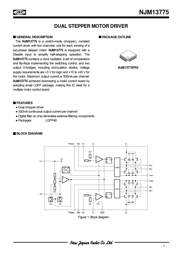
current driver with two channels: one for each winding of a two-phase stepper motor. NJM13775 is equipped with a Disable input to simplify half-stepping operation. The NJM13775 contains a clock oscillator, a set of comparators and flip-flops implementing the switching control, and two output H-bridges, including recirculation diodes.
Voltage supply requirements are +5 V for logic and +10 to +45 V for the motor. Maximum output current is 500mA per channel. NJM13775 achieved downsizing a motor control board by adopting small LQFP package, making this IC ideal for a multiple motor control board.
PACKAGE OUTLINE NJM13775FR3
FEATURES
● Dual chopper driver
● 350mA continuous output current per channel
● Digital filter on chip eliminates external filtering components
● Packages
LQFP48
BLOCK DIAGRAM
Figure 1. Block diagram Figure 1. Block diagram
-1-
NJM13775
PIN CONFIGURATION
GND NC
VMM1 NC
GND GND GND GND GND
NC VR1 C1
37 38 39 40 41 42 43 44 45 46 47 48
36 MA1 35 NC 34 E1 33 NC 32 MB1 31 NC 30 NC 29 MB2 28 NC 27 E2 26 NC 25 MA2
24 GND 23 NC 22 VMM2 21 NC 20 GND 19 GND 18 GND 17 GND 16 GND 15 NC 14 VR2 13 C2
NC 1 NC 2 Phase1 3 Dis1 4 RC 5 NC 6 VCC 7 NC 8 Dis2 9 NC 10 Phase2 11 NC 12
Figure 2. Pin configurations
PIN DESCRIPTION
PIN #
Symbol
32
34
36 39
16,17,18,19,20,24,37, 41,42,43,44,45
MB1 E1 MA1 VMM1 GND
47 VR1 48 C1
3 Phase1
4 Dis1 5 RC...