NTMFS6H800N
MOSFET – Power, Single, N-Channel
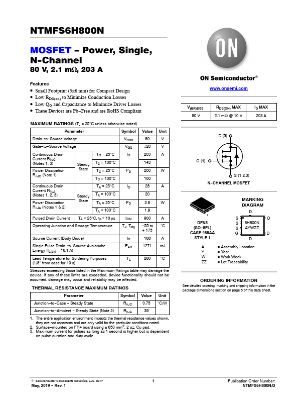
80 V, 2.1 mW, 203 A
Features
• Small Footprint (5x6 mm) for Compact Desi...
NTMFS6H800N
MOSFET – Power, Single, N-Channel
80 V, 2.1 mW, 203 A
Features
Small Footprint (5x6 mm) for Compact Design
Low RDS(on) to Minimize Conduction Losses Low QG and Capacitance to Minimize Driver Losses These Devices are Pb−Free and are RoHS Compliant
MAXIMUM RATINGS (TJ = 25°C unless otherwise noted)
Parameter
Symbol Value
Unit
Drain−to−Source
Voltage
Gate−to−Source
Voltage
Continuous Drain C(Nuortreesnt1R, 3qJ)C Power Dissipation RqJC (Note 1)
Steady State
TC = 25°C TC = 100°C TC = 25°C TC = 100°C
Continuous Drain C(Nuortreesnt1R, 2qJ,A3) Power Dissipation RqJA (Notes 1 & 2)
Steady State
TA = 25°C TA = 100°C TA = 25°C TA = 100°C
Pulsed Drain Current TA = 25°C, tp = 10 ms
Operating Junction and Storage Temperature
VDSS VGS ID
PD
ID
PD
IDM TJ, Tstg
80 ±20 203 143 200 100 28 20 3.8 1.9 900 −55 to + 175
V V A
W
A
W
A °C
Source Current (Body Diode)
IS 166 A
Single Pulse Drain−to−Source Avalanche Energy (IL(pk) = 16.1 A)
EAS 1271 mJ
Lead Temperature for Soldering Purposes (1/8″ from case for 10 s)
TL 260 °C
Stresses exceeding those listed in the Maximum Ratings table may damage the device. If any of these limits are exceeded, device functionality should not be assumed, damage may occur and reliability may be affected.
THERMAL RESISTANCE MAXIMUM RATINGS
Parameter
Symbol Value Unit
Junction−to−Case − Steady State
RqJC
0.75 °C/W
Junction−to−Ambient − Steady State (Note 2)
RqJA
39
1. The entire application environment impacts the the...