Power interface
Low-Z selection jumpers
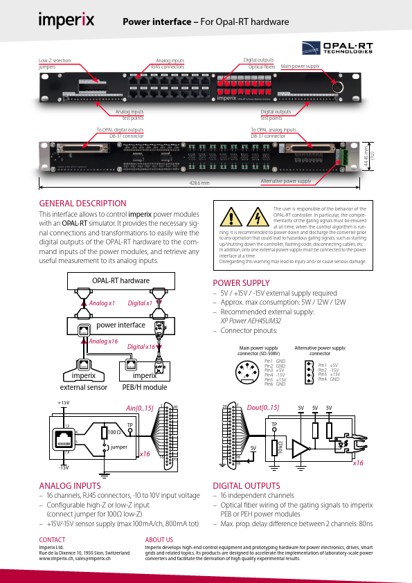
Power interface – For Opal-RT hardware
Analog inputs RJ45 connectors
Digital outputs Optical ...
Description
Low-Z selection jumpers
Power interface – For Opal-RT hardware
Analog inputs RJ45 connectors
Digital outputs Optical bers Main power supply
Analog inputs test points
To OPAL digital outputs DB-37 connector
Digital outputs test points
To OPAL analog inputs DB-37 connector
44.45 mm (1U)
Main power supply connector (SD-50BV)
Alternative power supply connector
428.6 mm
4 25
1
3
6
GENERAL DESCRIPTION
This interface allows to control imperix power modules
Pin1 GND
Pin2 GNADlternative powe1r supPpinly1 +5V
Pin3 +5V
2 Pin2 -15V
Pin4 -15V
3 Pin3 +15V
Pin5 +15V
Pin4 GND
4
Pin6 GND
The user is responsible of the behavior of the
OPAL-RT controller. In particular, the comple-
with an OPAL-RT simulator. It provides the necessary sig-
mentarity of the gating signals must be ensured at all time, when the control algorithm is run-
nal connections and transformations to easily wire the
digital outputs of the OPAL-RT hardware to the com-
cMomnanianencptdoowri(enSrDps-uu5p0tpsBlVyo) f the Apltoewrnaetcriovmennpeoocwdtoeurrlseusp,palynd retrieve any
useful mePains1urGeNmDent to its analog inputs.
4 25
Pin2 GND Pin3 +5V
1 Pin1 +5V 2 Pin2 -15V
1
3
6
Pin4 Pin5
-15V +15V
OPAL-RT3 4
haPPriinnd34w+Ga1Nr5DeV
Pin6 GND
Analog x1 Digital x1
from imperix
power interface
to OPAL
ning. It is recommended to power down and discharge the converter prior
to any operation that could lead to hazardous gating signals, such as starting
up/shufrttoinmg idmowpenrtihxe co...
Similar Datasheet