![]() |
MOSFET. S90N045R Datasheet |
|
![]() SI-TECH SEMICONDUCTOR CO.,LTD
S90N045R/S
N-Channel MOSFET
Features
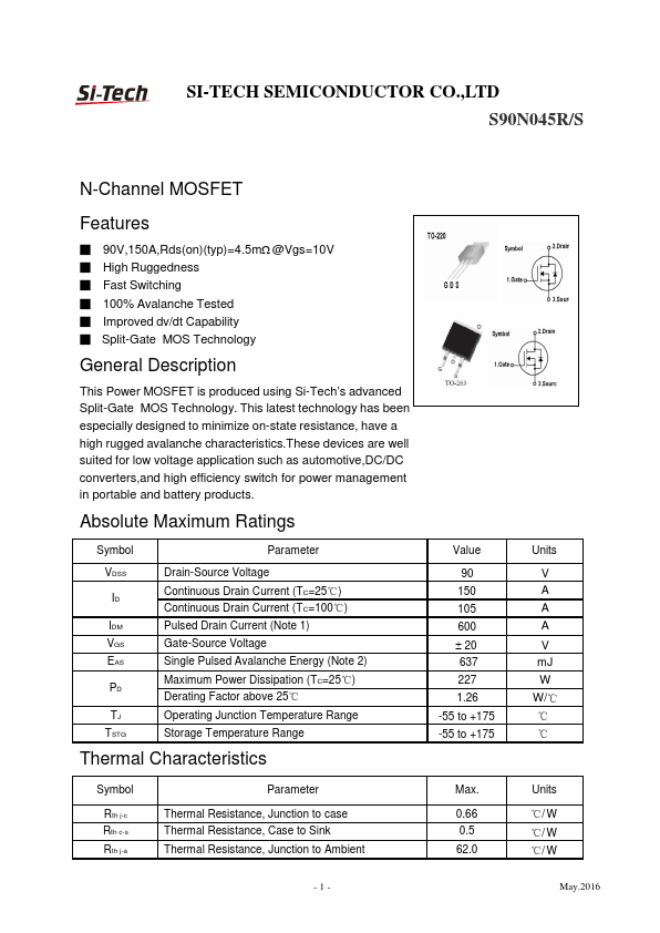
█ 90V,150A,Rds(on)(typ)=4.5mΩ @Vgs=10V
█ High Ruggedness
█ Fast Switching
█ 100% Avalanche Tested
█ Improved dv/dt Capability
█ Split-Gate MOS Technology
General Description
This Power MOSFET is produced using Si-Tech’s advanced
Split-Gate MOS Technology. This latest technology has been
especially designed to minimize on-state resistance, have a
high rugged avalanche characteristics.These devices are well
suited for low voltage application such as automotive,DC/DC
converters,and high efficiency switch for power management
in portable and battery products.
Absolute Maximum Ratings
Symbol
Parameter
VDSS
ID
IDM
VGS
EAS
PD
TJ
TSTG
Drain-Source Voltage
Continuous Drain Current (TC=25℃)
Continuous Drain Current (TC=100℃)
Pulsed Drain Current (Note 1)
Gate-Source Voltage
Single Pulsed Avalanche Energy (Note 2)
Maximum Power Dissipation (TC=25℃)
Derating Factor above 25℃
Operating Junction Temperature Range
Storage Temperature Range
Thermal Characteristics
Symbol
Rth j-c
Rth c-s
Rth j-a
Parameter
Thermal Resistance, Junction to case
Thermal Resistance, Case to Sink
Thermal Resistance, Junction to Ambient
Value
90
150
105
600
± 20
637
227
1.26
-55 to +175
-55 to +175
Max.
0.66
0.5
62.0
-1-
Units
V
A
A
A
V
mJ
W
W/℃
℃
℃
Units
℃/ W
℃/ W
℃/ W
May.2016
|
|
![]() SI-TECH SEMICONDUCTOR CO.,LTD
S90N045R/S
Electrical Characteristics (TC=25℃ unless otherwise noted)
Symbol
Parameter
BVDSS
IDSS
IGSS
VGS(th)
RDS(on)
Qg
Qgs
Qgd
t d(on)
tr
t d(off)
tf
Ciss
Coss
Crss
Drain-Source Breakdown Voltage
Drain-Source Leakage Current
Gate Leakage Current, Forward
Gate Leakage Current, Reverse
Gate Threshold Voltage
Drain-Source On-State Resistance
Total Gate Charge
Gate-Source Charge
Gate-Drain Charge
Turn-on Delay Time
Turn-on Rise Time
Turn-off Delay Time
Turn-off Fall Time
Input Capacitance -
Output Capacitance
Reverse Transfer Capacitance
Test Conditions
VGS=0V, ID=250uA
VDS=72V, VGS=0V
VGS=20V, VDS=0V
VGS=-20V, VDS=0V
VGS=VDS, ID=250uA
VGS=10V, ID=40A
VDD=40V
VGS=10V
ID=50A
(Note 3)
VDD=40V,VGS=10V
ID=45A,RG=3Ω
TC=25℃
(Note 3)
VDS=0V
VGS=0V
f = 1MHz
Min. Typ. Max. Units
90 -
-V
- - 1 uA
- - 100 nA
- - -100 nA
2 3 4V
- 4.5 5.5 m Ω
- 55 - nC
- 15
- nC
- 13
- nC
- 20.1 - ns
- 38.9 - ns
- 45.1 - ns
- 22.8 - ns
- 3086 -
pF
- 1057 -
pF
- 26.0 - pF
Source-Drain Diode Characteristics (TC=25℃ unless otherwise noted)
Symbol
Parameter
Test Conditions
IS Continuous Source Diode Forward Current
ISM Pulsed Source Diode Forward Current (Note 1)
VSD Forward On Voltage
VGS=0V, IS=45A
tr r Reverse Recovery Time
VGS=0V, IS=45A
Qr r Reverse Recovery Charge
dIF/dt = 100A/us
Notes:
1. Repetitive Rating: Pulse width limited by maximum junction temperature
2. L=0.5mH, VDD=50V, RG=25 Ω, Starting TJ=25℃
3. Pulse Width ≤ 300 us; Duty Cycle≤2%
Min. Typ. Max. Units
- - 120 A
- - 480 A
- 0.95 1.4
V
- 60
- ns
- 56
- nC
- 2 - May.2016
|
![]() SI-TECH SEMICONDUCTOR CO.,LTD
S90N045R/S
Typical Characteristics
Output Characteristics
Drain Current
VDS - Drain-Source Voltage (V)
Safe Operation Area
T j- Junction Temperature (°C)
Thermal Transient Impedance
V DS- Drain-Source Voltage (V)
-3-
Square Wave Pulse Duration (sec)
May.2016
|
@ 2014 :: Datasheetspdf.com :: Semiconductors datasheet search & download site (Privacy Policy & Contact) |