D 2-V to 6-V VCC Operation D Inputs Accept Voltages to 6 V D Max tpd of 7 ns at 5 V
SN54AC00 . . . J OR W PACKAGE SN74AC...
D 2-V to 6-V VCC Operation D Inputs Accept
Voltages to 6 V D Max tpd of 7 ns at 5 V
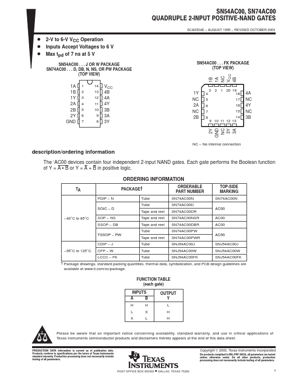
SN54AC00 . . . J OR W PACKAGE SN74AC00 . . . D, DB, N, NS, OR PW PACKAGE
(TOP VIEW)
1A 1 1B 2 1Y 3 2A 4 2B 5 2Y 6 GND 7
14 VCC 13 4B 12 4A 11 4Y 10 3B 9 3A 8 3Y
SN54AC00, SN74AC00 QUADRUPLE 2ĆINPUT POSITIVEĆNAND GATES
SCAS524E − AUGUST 1995 − REVISED OCTOBER 2003
SN54AC00 . . . FK PACKAGE (TOP VIEW)
4B
VCC
NC
1A
1B
3 2 1 20 19
1Y 4
18 4A
NC 5
17 NC
2A 6
16 4Y
NC 7
15 NC
2B 8
14 3B
9 10 11 12 13
3A
3Y
NC
GND
2Y
description/ordering information
NC − No internal connection
The ‘AC00 devices contain four independent 2-input NAND gates. Each gate performs the Boolean function of Y = A S B or Y = A + B in positive logic.
ORDERING INFORMATION
TA
PACKAGE†
ORDERABLE PART NUMBER
TOP-SIDE MARKING
PDIP − N
Tube
SN74AC00N
SN74AC00N
SOIC − D
Tube Tape and reel
SN74AC00D SN74AC00DR
AC00
−40°C to 85°C
SOP − NS SSOP − DB
Tape and reel Tape and reel
SN74AC00NSR SN74AC00DBR
AC00 AC00
TSSOP − PW
Tube Tape and reel
SN74AC00PW SN74AC00PWR
AC00
CDIP − J
Tube
SNJ54AC00J
SNJ54AC00J
−55°C to 125°C CFP − W
Tube
SNJ54AC00W
SNJ54AC00W
LCCC − FK
Tube
SNJ54AC00FK
SNJ54AC00FK
† Package drawings, standard packing quantities, thermal data, symbolization, and PCB design guidelines are available at www.ti.com/sc/package.
FUNCTION TABLE (each gate)
INPUTS
A
B
H
H
L
X
X
L
OUTPUT Y L H H
Please be aware that an important notice concerning availability, stan...