SN54AHCT74, SN74AHCT74
SCLS263Q – DECEMBER 1995 – REVISED JULY 2023
SNxAHCT74 Dual Positive-Edge-Triggered D-Type Flip-F...
SN54AHCT74, SN74AHCT74
SCLS263Q – DECEMBER 1995 – REVISED JULY 2023
SNxAHCT74 Dual Positive-Edge-Triggered D-Type Flip-Flops With Clear And Preset
1 Features
Operating range of 4.5 V to 5.5 V Low power consumption, 10-µA maximum ICC ±8-mA output drive at 5 V Inputs are TTL-
voltage compatible Latch-up performance exceeds 250 mA per JESD
17
2 Applications
Convert a momentary switch to a toggle switch Hold a signal during controller reset Input slow edge-rate signals Operate in noisy environments Divide a clock signal by two
3 Description
The ’AHCT74 dual positive-edge-triggered devices are D-type flip-flops.
A low level at the preset (PRE) or clear (CLR) inputs sets or resets the outputs, regardless of the levels of the other inputs. When PRE and CLR are inactive (high), data at the data (D) input meeting the setup time requirements is transferred to the outputs on the positive-going edge of the clock pulse. Clock triggering occurs at a
voltage level and is not directly related to the rise time of the clock pulse. Following the hold-time interval, data at the D input can be changed without affecting the levels at the outputs.
PART NUMBER SN54AHCT74
SN74AHCT74
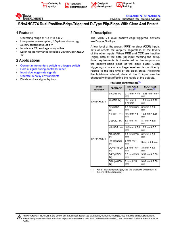
Package Information(1)
PACKAGE
PACKAGE SIZE(1)
BODY SIZE (NOM)(1)
J (CDIP, 14) 21.3 mm × 7.6 19.56 mm × 6.67
mm
mm
W (CFP, 14) 13.1 mm × 6.92 mm
13.1 mm × 6.92 mm
FK (LCCC, 20)
8.9 mm × 8.9 8.9 mm × 8.9
mm
mm
N (PDIP , 14) 19.3 mm × 8 19.3 mm × 6.35
mm
mm
D (SOIC, 14) 8.7 mm × 6 mm...