www.vishay.com
SiZF918DT
Vishay Siliconix
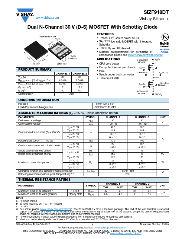
Dual N-Channel 30 V (D-S) MOSFET With Schottky Diode
PRODUCT SUMMARY
VDS (V...
www.vishay.com
SiZF918DT
Vishay Siliconix
Dual N-Channel 30 V (D-S)
MOSFET With Schottky Diode
PRODUCT SUMMARY
VDS (V) RDS(on) max. (Ω) at VGS = 10 V RDS(on) max. (Ω) at VGS = 4.5 V Qg typ. (nC) ID (A) a Configuration
CHANNEL-1 CHANNEL-2
30 30
0.0040
0.0019
0.0067
0.0027
7 17.3
40 60
Dual
FEATURES TrenchFET® Gen IV power
MOSFET SkyFET® low side
MOSFET with integrated
Schottky
100 % Rg and UIS tested Material categorization: for definitions of
compliance please see www.vishay.com/doc?99912
APPLICATIONS CPU core power
N-Channel 1
MOSFET
Computer / server peripherals GHS/G1 POL Synchronous buck converter G1Return/S1
Telecom DC/DC
VIN/D1 VSW/S1-D2
GLS/G2
Schottky Diode
N-Channel 2
MOSFET
GND/S2
ORDERING INFORMATION
Package Lead (Pb)-free and halogen-free
PowerPAIR 6 x 5F SiZF918DT-T1-GE3
ABSOLUTE MAXIMUM RATINGS (TA = 25 °C, unless otherwise noted)
PARAMETER
SYMBOL
CHANNEL-1
CHANNEL-2
Drain-source
voltage
Gate-source
voltage
Continuous drain current (TJ = 150 °C) Pulsed drain current (t = 100 μs)
TC = 25 °C TC = 70 °C TA = 25 °C TA = 70 °C
Continuous source-drain diode current
Single pulse avalanche current Single pulse avalanche energy
TC = 25 °C TA = 25 °C
L = 0.1 mH
TC = 25 °C
Maximum power dissipation
TC = 70 °C TA = 25 °C
TA = 70 °C
Operating junction and storage temperature range
Soldering recommendations (peak temperature) d, e
VDS VGS
ID
IDM IS IAS EAS
PD
TJ, Tstg
30 +20, -16
40 a 40 a 23 b, c 18.4 b, c 130 22 2...