D 8-Bit Resolution A/D Converter D Microprocessor Peripheral or Stand-Alone
Operation
D On-Chip 20-Channel Analog Multip...
D 8-Bit Resolution A/D Converter D Microprocessor Peripheral or Stand-Alone
Operation
D On-Chip 20-Channel Analog Multiplexer D Built-in Self-Test Mode D Software-Controllable Sample and Hold D Total Unadjusted Error . . . ± 0.5 LSB Max D Timing and Control Signals Compatible
With 8-Bit TLC540 and 10-Bit TLC1540 A/D
Converter Families
D
CMOS Technology
PARAMETER
Channel Acquisition Time Conversion Time (Max) Sampling Rate (Max) Power Dissipation (Max)
TL545
1.5 µs 9 µs 76 x 103 15 mW
TL546
2.7 µs 17 µs 40 x 103 15 mW
TLC545C, TLC545I, TLC546C, TLC546I 8-BIT ANALOG-TO-DIGITAL CONVERTERS
WITH SERIAL CONTROL AND 19 INPUTS
SLAS066B – DECEMBER 1985 – REVISED OCTOBER 1996
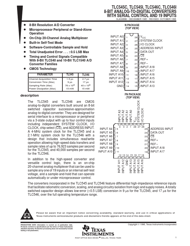
N PACKAGE (TOP VIEW)
INPUT A0 INPUT A1 INPUT A2 INPUT A3 INPUT A4 INPUT A5 INPUT A6 INPUT A7 INPUT A8 INPUT A9 INPUT A10 INPUT A11 INPUT A12
GND
1 2 3 4 5 6 7 8 9 10 11 12 13 14
28 VCC 27 SYSTEM CLOCK 26 I/O CLOCK 25 ADDRESS INPUT 24 DATA OUT 23 CS 22 REF + 21 REF – 20 INPUT A18 19 INPUT A17 18 INPUT A16 17 INPUT A15 16 INPUT A14 15 INPUT A13
description
The TLC545 and TLC546 are
CMOS analog-to-digital converters built around an 8-bit switched capacitor successive-approximation analog-to-digital converter. They are designed for serial interface to a microprocessor or peripheral via a 3-state output with up to four control inputs including independent SYSTEM CLOCK, I/O CLOCK, chip select (CS), and ADDRESS INPUT. A 4-MHz system clock for the TLC545 and a 2.1-MHz system clock for the TLC546 with a design that...