D Configured for 3-Phase Brushless Motor
Drive
D Low rDS(on) . . . 0.25 Ω Typ D High Voltage Output . . . 30 V D Pulsed ...
D Configured for 3-Phase Brushless Motor
Drive
D Low rDS(on) . . . 0.25 Ω Typ D High
Voltage Output . . . 30 V D Pulsed Current . . . 12 A Per Channel D Input Transient and ESD Protection D Compatible With High-Side and Low-Side
Current Sense Resistors
description
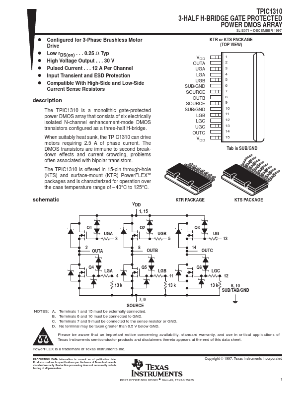
The TPIC1310 is a monolithic gate-protected power DMOS array that consists of six electrically isolated N-channel enhancement-mode DMOS transistors configured as a three-half H-bridge.
When suitably heat sunk, the TPIC1310 can drive motors requiring 2.5 A of phase current. The DMOS transistors are immune to second breakdown effects and current crowding, problems often associated with bipolar transistors.
The TPIC1310 is offered in 15-pin through-hole (KTS) and surface-mount (KTR) PowerFLEX™ packages and is characterized for operation over the case temperature range of – 40°C to 125°C.
schematic
VDD 1, 15
TPIC1310 3-HALF H-BRIDGE GATE PROTECTED
POWER DMOS ARRAY
SLIS071 – DECEMBER 1997
KTR or KTS PACKAGE (TOP VIEW)
VDD OUTA
UGA LGA UGB SUB/GND SOURCE OUTB SOURCE SUB/GND LGB LGC UGC OUTC VDD
1 2 3 4 5 6 7 8 9 10 11 12 13 14 15
Tab is SUB/GND
KTR PACKAGE
KTS PACKAGE
Q1 UGA 3
2 OUTA
Q2 UGB 5
8 OUTB
Q3 UG C 13
14 OUTC
Q4 LGA
4
Q5 LGB
11
Q6 LGC
12
13 k 13 k 13 k 6, 10 SUB/TAB/GND
7, 9 SOURCE NOTES: A. Terminals 1 and 15 must be externally connected. B. Terminals 6 and 10 must be connected to GND. C. Terminals 7 and 9 must be connected to the sense resistor or GND. D. No terminal may be taken greater than 0....