p-channel JFETs
designed for • • •
• Analog Switches • Commutators • Choppers
H
Siliconix
Performance Curves PSA/PSB/PS...
p-channel JFETs
designed for
Analog Switches Commutators Choppers
H
Siliconix
Performance Curves PSA/PSB/PSC See Section 4
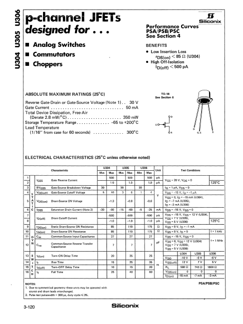
BENEFITS
Low Insertion Loss
rDSlon) < 85 n (U304)
High Off-Isolation
ID(off) < 500 pA
ABSOLUTE MAXIMUM RATINGS (25°C)
Reverse Gate-Drain or Gate-Source
Voltage (Note 1) .. 30V
Gate Current ............................... 50mA
Total Device Dissipation, Free-Air
(Derate 2.8 mW/oC) ....................... 350mW
Storage Temperature Range .............. -65 to +200°C
Lead Temperature (1/16" from case for 60 seconds)
............ .
300°C
TO-18 See Section 6
.~:
U
~;rr
D G~C
ELECTRICAL CHARACTERISTICS (25°C unless otherwise noted)
Characteristic
1
12" IGSS
3- '
~ ::
T
5A T
6- '
I C
-7
8
BVGSS VGSlnffl
VOS(on)
lOSS
I o(off)
"9 'OS(on)
10 'ds(on)
22: 0 CISS Y 12 N Crss
Gate Reverse Current
Gate-Source Breakdown
Voltage Gate-Source Cutoff
Voltage
Drain-Source ON
Voltage
SaturatIon Drain Current (Note 2)
Drain Cutoff Current
Static Dram-Source ON Resistance Drain-Source ON ReSistance Common-Source Input Capacitance Common-Source Reverse Transfer Capacitance
13 S td(on)
14
W I
t,
15 T 1e c
H
teI(off) tf
Turn-ON Delay Time
Rise Time Turn-OFF Delay Time Fall Time
U304 Min Max
500 10 30 5 10
-1.3
-30 -90 -500 -1.0 B5 85 27
7
20 15 10 25
U305 Min Max
500 1.0 30 36
-0.8
-15 -60 -500 -1.0 110 110 27
7
25 25 15 40
U306 Unit
Min Max 500 pA 1.0 p.A
30 11 V -0.6
-5 -25 mA -500 pA -1.0 p.A 175 n 175 n 27 pF 7
25
35 ns
20 60
...