IGBT Modules
VDI130-06P1 VII 130-06P1 VID130-06P1 VIO130-06P1
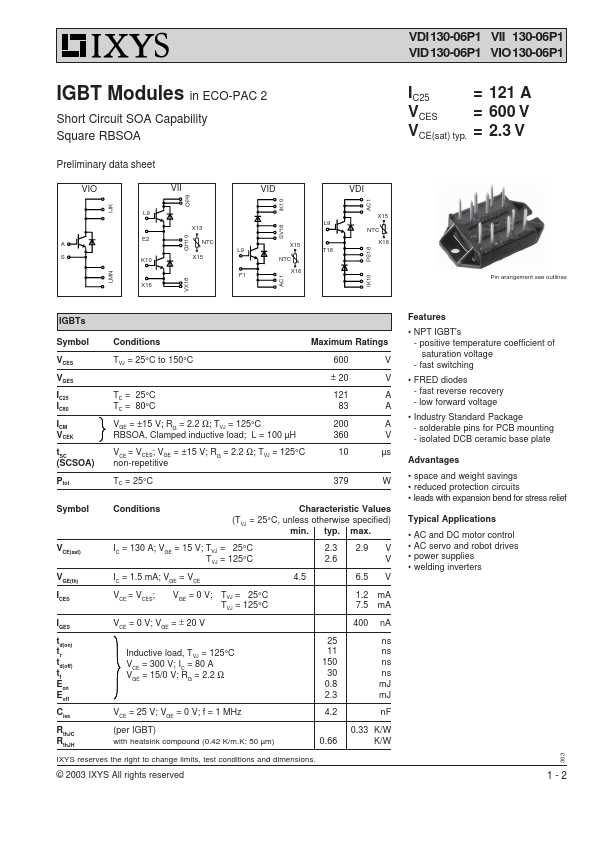
IGBT Modules in ECO-PAC 2
Short Circuit SOA Capability Square RBSOA
I...
Description
VDI130-06P1 VII 130-06P1 VID130-06P1 VIO130-06P1
IGBT Modules in ECO-PAC 2
Short Circuit SOA Capability Square RBSOA
IC25 = 121 A
VCES
= 600 V
VCE(sat) typ. = 2.3 V
LMN IJK
Preliminary data sheet
VIO VII
L9 X13
A E2 NTC S K10 X15
X16
GH10
OP9
AC1
VID VDI
AC1
SV18 IK10
X15
L9 NTC
X15 L9 T16
NTC
X16
X16 F1
IK10 PS18
B3
Pin arangement see outlines
VX18
IGBTs
Symbol
VCES
VGES
IC25 IC80
ICM VCEK
tSC (SCSOA)
Ptot
Conditions
Maximum Ratings
TVJ = 25°C to 150°C
600 V ± 20 V
TC = 25°C TC = 80°C
121 A 83 A
VGE = ±15 V; RG = 2.2 Ω; TVJ = 125°C
200 A
RBSOA, Clamped inductive load; L = 100 µH 360 V
VCE = VCES; VGE = ±15 V; RG = 2.2 Ω; TVJ = 125°C 10 µs non-repetitive
TC = 25°C
379 W
Symbol
Conditions
Characteristic Values
(TVJ = 25°C, unless otherwise specified) min. typ. max.
VCE(sat)
IC = 130 A; VGE = 15 V; TVJ = 25°C TVJ = 125°C
2.3 2.6
V GE(th)
I = 1.5 mA; V = V
C GE CE
4.5
ICES VCE = VCES; VGE = 0 V; TVJ = 25°C TVJ = 125°C
IGES VCE = 0 V; VGE = ± 20 V
td(on) t
r
td(off) t
f
Eon Eoff
Inductive load, TVJ = 125°C V = 300 V; I = 80 A
CE C
VGE = 15/0 V; RG = 2.2 Ω
25 11 150 30 0.8 2.3
C V = 25 V; V = 0 V; f = 1 MHz ies CE GE
4.2
RthJC RthJH
(per IGBT) with heatsink compound (0.42 K/m.K; 50 µm)
0.66
IXYS reserves the right to change limits, test conditions and dimensions.
2.9 V V
6.5 V
1.2 mA 7.5 mA
400 nA
ns ns ns ns mJ mJ
nF
0.33 K/W K/W
© 2003 IXYS All rights reserved
Features NPT IGBT's
- positive temperature coefficient of satu...
Similar Datasheet