IGBT Module
Sixpack in ECO-PAC 2
VWI 6-12P1
IC25 = 6 A
VCES
= 1200 V
VCE(sat) typ. = 3.9 V
Preliminary data
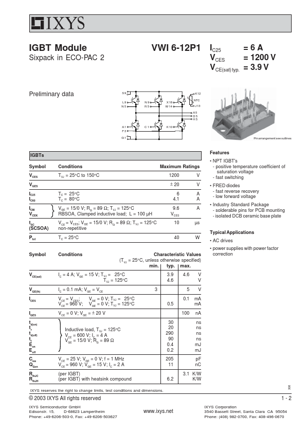
S9 L ...
IGBT Module
Sixpack in ECO-PAC 2
VWI 6-12P1
IC25 = 6 A
VCES
= 1200 V
VCE(sat) typ. = 3.9 V
Preliminary data
S9 L 9 N 9 X 18 N 5 R 5 W 14
A 1 C 1 K 10 F3 G1
K 12
NTC J 13
A5 D5 H5
Pin arrangement see outlines
IGBTs
Symbol VCES VGES IC25 IC80 ICM VCEK tSC (SCSOA) Ptot
Symbol
Conditions
Maximum Ratings
TVJ = 25°C to 150°C
1200 ± 20
V V
TC = 25°C TC = 80°C
VGE
=
15/0
V;
R G
=
89
Ω;
TVJ
=
125°C
RBSOA, Clamped inductive load; L = 100 µH
VCE = VCES; VGE = 15/0 V; RG = 89 Ω; TVJ = 125°C non-repetitive
6 4.1
9.6 VCES
10
A A A
µs
TC = 25°C
40 W
Conditions
Characteristic Values
(TVJ = 25°C, unless otherwise specified) min. typ. max.
Features
NPT IGBT's - positive temperature coefficient of saturation
voltage - fast switching
FRED diodes - fast reverse recovery - low forward
voltage
Industry Standard Package - solderable pins for PCB mounting - isolated DCB ceramic base plate
Typical Applications
AC drives
power supplies with power factor correction
V CE(sat)
VGE(th)
ICES
IGES
td(on) t
r
td(off) t
f
Eon Eoff
C ies
QGon
RthJC R
thJH
I
C
=
4
A;
V GE
=
15
V;
TVJ
=
25°C
TVJ = 125°C
IC = 0.1 mA; VGE = VCE
VCE = VCES; VGE = 0 V; TVJ = 25°C VCE = 960 V; VGE = 0 V; TVJ = 125°C
VCE = 0 V; VGE = ± 20 V
Inductive load, TVJ = 125°C
VCE = 600 V; IC = 4 A
V GE
=
15/0
V;
R G
=
89
Ω
V = 25 V; V = 0 V; f = 1 MHz CE GE
VCE = 960 V; VGE = 15 V; IC = 2 A
(per IGBT) (per IGBT) with heatsink compound
3.9 4.6 V 4.6 V
3 5V
0.1 mA 0.5 mA
10...