NS ESIG D N EW CT F O R PR O D U D E E ND UT E Data Sheet O M M U B S TI T C E S R 0 9582 NOT SSIBLE X PO
®
X9269
Singl...
NS ESIG D N EW CT F O R PR O D U D E E ND UT E Data Sheet O M M U B S TI T C E S R 0 9582 NOT SSIBLE X PO
®
X9269
Single Supply/Low Power/256-Tap/2-Wire Bus
April 17, 2007 FN8173.4
Dual Digitally-Controlled (XDCP™) Potentiometers
FEATURES Dual–Two Separate Potentiometers 256 Resistor Taps/Pot–0.4% Resolution 2-Wire Serial Interface for Write, Read, and Transfer Operations of the Potentiometer Single Supply Device Wiper Resistance, 100Ω Typical VCC = 5V 4 Nonvolatile Data Registers for Each Potentiometer Nonvolatile Storage of Multiple Wiper Positions Power-on Recall. Loads Saved Wiper Position on Power-up. Standby Current < 5µA Max 50kΩ, 100kΩ Versions of End to End Pot Resistance 100 yr. Data Retention Endurance: 100,000 Data Changes per Bit per Register 24-Lead SOIC, 24-Lead TSSOP Low Power
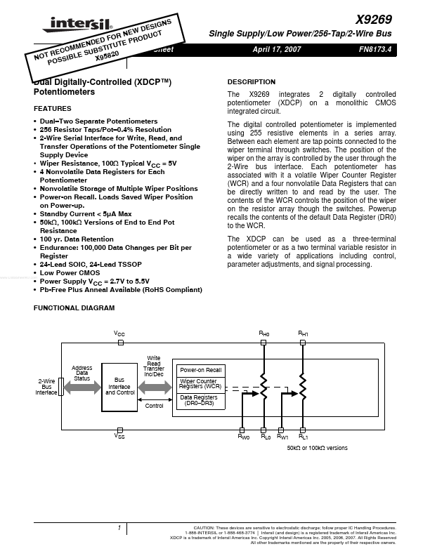
CMOS www.DataSheet4U.com Power Supply VCC = 2.7V to 5.5V Pb-Free Plus Anneal Available (RoHS Compliant) FUNCTIONAL DIAGRAM
DESCRIPTION The X9269 integrates 2 digitally controlled potentiometer (XDCP) on a monolithic
CMOS integrated circuit. The digital controlled potentiometer is implemented using 255 resistive elements in a series array. Between each element are tap points connected to the wiper terminal through switches. The position of the wiper on the array is controlled by the user through the 2-Wire bus interface. Each potentiometer has associated with it a volatile Wiper Counter Register (WCR) and a four nonvolatile Data Registers that can be direc...