www. DataSheet4U. com
UNISONIC TECHNOLOGIES CO. , LTD DTA123E
PNP EPITAXIAL SILICON TRANSISTOR
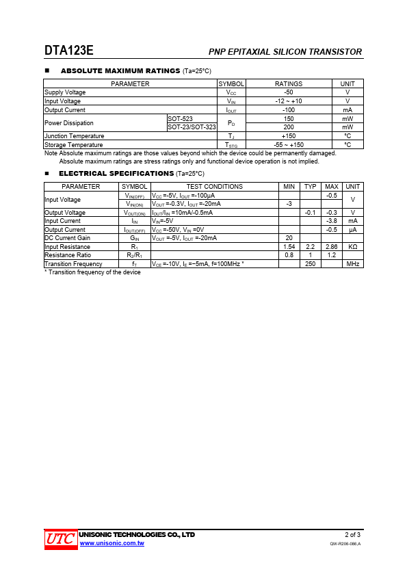
3
DIGITAL TRANSISTORS (BUILT- IN BIAS RESISTORS)
FEATURES
* Built-in bias resistors that implies easy ON/OFF applications. * The bias resistors are thin-film resistors with complete isolation to allow positive input.
2 3
1
SOT-23
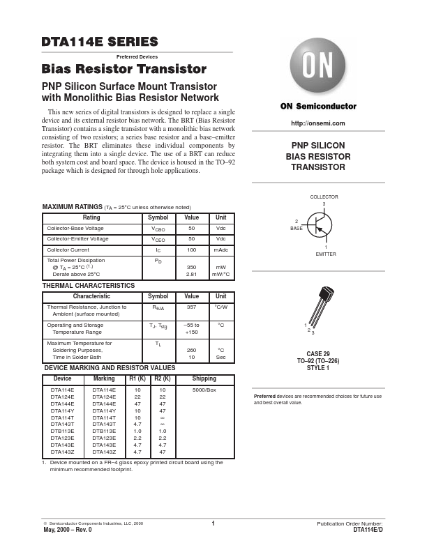
EQUIVALENT CIRCUIT
R1 IN R2 OUT
2 3
1
SOT-323
2
GND IN GND OUT
1
SOT-523
*Pb-free plating product number:DTA123EL
ORDERING INFORMATION
Order Number Normal Lead Free Plating DTA123E-AE3-6-R DTA123EL-AE3-6-R DTA123E-AL3-6-R DTA123EL-AL3-6-R DTA123E-AN3-6-R DTA123EL-AN3-6-R Package SOT-23 SOT-323 SOT-523 Pin Assignment 1 2 3 G I O G I O G I O Packing Tape Reel Tape...