Power Diodes
Controlled Avalanche
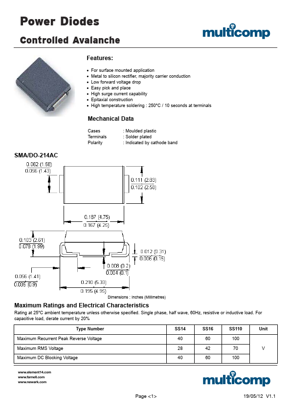
Features:
• • • • • • • For surface mounted application Metal to silicon rectifier, majority carrier conduction Low forward voltage drop Easy pick and place High surge current capability Epitaxial construction High temperature soldering : 250°C / 10 seconds at terminals
Mechanical Data
Cases Terminals Polarity : Moulded plastic : Solder plated : Indicated by cathode band
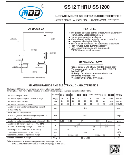
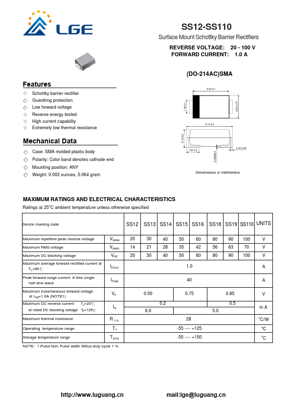
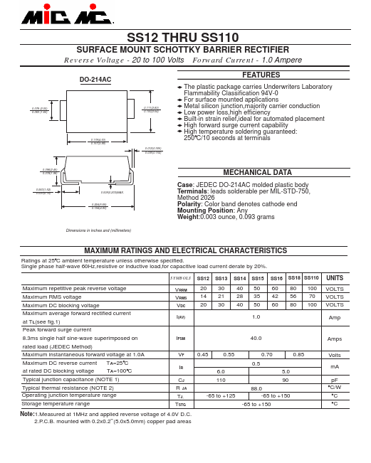
SMA/DO-214AC
Dimensions : Inches (Millimetres)
Maximum Ratings and Electrical Characteristics
Rating at 25°C ambient temperature unless otherwise specified. Single phase, half wave, 60Hz, resistive or inductive load. For capacitive load, derate current by 20% Type Number Maximum Recurren...